66
“3+1” AUDIO DOOR ENTRY SYSTEMS
SISTEMI CITOFONICI “3+1”
ONE MAIN ENTRANCE PLUS THREE
SECONDARY ENTRANCES AUDIO DOOR
ENTRY SYSTEM
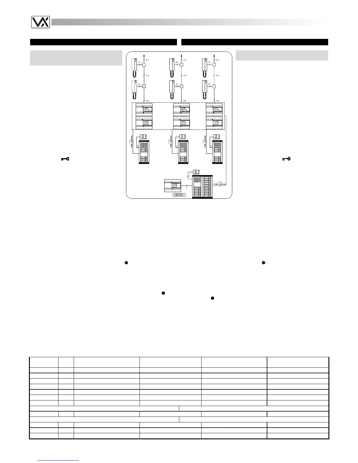
The diagram shows a system suitable for
residential estates which have one main
entrance and more secondary entrances like
residences, holiday camps or big block of
flats. In these cases the system should allows
to call all users from the main entrance and
only the relevant users from secondary
entrances.
Operation
- The visitor calls the requested user by
pressing the relevant button on the outdoor
station (from one secondary entrance or
from the main one);
- The called intercom will ring until the button
is pressed;
- The called user can answer by picking up
the handset and then can open the door by
pressing the
push button whether the
call come from the main entrance or from a
secondary one;
- The system will be switched off hanging up
the handset;
- The secondary entrances are independent
so it is possible to speak at the same time
from each one with the relevant users.
IMPIANTO CITOFONICO AD UN INGRESSO
PRINCIPALE E 3 INGRESSI SECONDARI
Lo schema mostra un impianto adatto a
complessi abitativi con un ingresso principale
e più ingressi secondari come residences,
villaggi turistici o grandi condomini. In queste
installazioni, l’impianto deve essere tale da
poter contattare dall’ingresso principale tutti gli
utenti e solo quelli interessati dagli ingressi
secondari.
Funzionamento
- Il visitatore, dall’ingresso principale o
secondario, chiama l’utente desiderato
premendo il relativo pulsante sul posto
esterno;
- Il citofono chiamato emette una nota
elettronica;
- L’utente può instaurare la conversazione
sollevando la cornetta ed aprire la porta
premendo il pulsante
(sia che l’ingresso
sia quello principale che quello secondario);
- Riagganciando la cornetta l’impianto si
spegne;
- Gli ingressi secondari sono indipendenti per
cui è possibile parlare da ciascuno di essi
contemporaneamente.
Installing the system
a. Consult the table below to obtain the items required. Regarding the
number of modules and the relevant housing (flush or surface), refer
to the section of this manual relevant to the 800 series modular
system;
b. Run the correct size cables (see page 25). See block diagram for
number of cores.
c. Test installation (see page 25) and in case of any problem see the
troubleshooting guide of this manual (see page 26).
Extra services and accessories
It is possible to install on the system additional accessories or/and have
extra services by using the service push button
:
1. Installation of an extension sounder (see page 23 fig.1);
2. Installation of a digital codelock module (see page 38 fig.2);
3. Installation of a proximity key reader module to open the door using
proximity keys (see page 38 fig.1);
4. Enable extra services like stair lights or gate opening through an
enslavement relay controlled by the service push button
(see
page 23 fig.5 and page 24 fig.9).
Realizzazione dell’impianto
a. Consultare la tabella di fondo pagina per il materiale occorrente: per
il numero dei moduli necessari e per il tipo ed il numero dei supporti
(da incasso o superficie) da utilizzare per contenerli, fare riferimento
alla sezione, del presente manuale, relativa al sistema modulare
serie 800;
b. Posare il cavo rispettando le sezioni dei fili (vedi pag.25);
c. Eseguire il collaudo dell’impianto (vedi pag.25) ed in caso di problemi
consultare la ricerca guasti del presente manuale (vedi pag.26)
Accessori e Servizi Ausiliari
È possibile installare nell’impianto degli accessori aggiuntivi e/o usufruire
di servizi ausiliari utilizzando il pulsante
:
1. Installazione di una suoneria supplementare (vedi pag.23 fig.1);
2. Installazione di un modulo “apri-porta” a codice (vedi pag.38 fig.2);
3. Installazione di un modulo lettore chiavi di prossimità codificate (vedi
pag.38 fig.1);
4. Attivazione di servizi ausiliari come luci scale (o apertura cancello
ecc.) tramite un relè d’asservimento comandato dal
pulsante
(vedi pag.23 fig.5 e 24 fig.9).
Notes
The call from the main entrance switches the speech lines and the “door
open” service from the secondary entrance relevant to the called user to it.
To make the switching, push button commons relevant to each staircase
are linked together and to the “A2” terminal of the relevant entrances
switch while to all the “A1” terminals is connected the call tone output “C1”
coming from the main entrance. Depending on the group of the push
button pressed on the main outdoor station the switching is to staircase
“A”, “B” or “C”.
Note
La chiamata dall’ingresso principale provoca la commutazione automatica
della linea fonica e del servizio di “apertura-porta”, dall’ingresso locale
relativo all’utente chiamato a quello principale. Per ottenere la
commutazione, i comuni dei pulsanti relativi a ciascuna scala sono stati
collegati tra di loro e al morsetto “A2” del relativo scambiatore, mentre al
morsetto “A1” di tutti gli scambiatori è stata collegata l’uscita della nota
elettronica “C1” proveniente dal posto esterno principale. In base al
gruppo di appartenenza del pulsante premuto sul posto esterno principale,
avviene la commutazione verso la scala “A”, “B” o “C”.
Art.
Qty
Qta
Description Notes Descrizione Note
3111 15
Intercom n = Intercoms in the system
Citofono n = Citofoni nell’impianto
837M-0 1
Speaker unit module
Modulo portiere elettrico
837M-2 3
Speaker unit module
Modulo portiere elettrico
843 3
Extension front panel module qty depend by extensions
Modulo pulsantiera qta in base al nr. di interni
845 3
Extension front panel module qty depend by extensions
Modulo pulsantiera qta in base al nr. di interni
520M 4
Power Supply Unit
Alimentatore
502N 3
Audio Entrances Switch
one each one outdoor station Scambiatore di Ingressi Audio uno ogni posto esterno
For outdoor station surface mount Per l’installazione da superficie del posto esterno
882-889 x
Surface mounting unit qty depend by nr of modules
Scatola di protezione qta in base al nr. moduli
For outdoor station flush mount Per l’installazione da incasso del posto esterno
852-853 x
Front support qty depend by nr of modules
Supporto frontale qta in base al nr. moduli
862-869 or x
Covering frame qty depend by nr of modules
Cornici di protezione qta in base al nr. moduli
872-879 x
Rainshield qty depend by nr of modules
Tettuccio antipioggia qta in base al nr. moduli
 Loading...