44
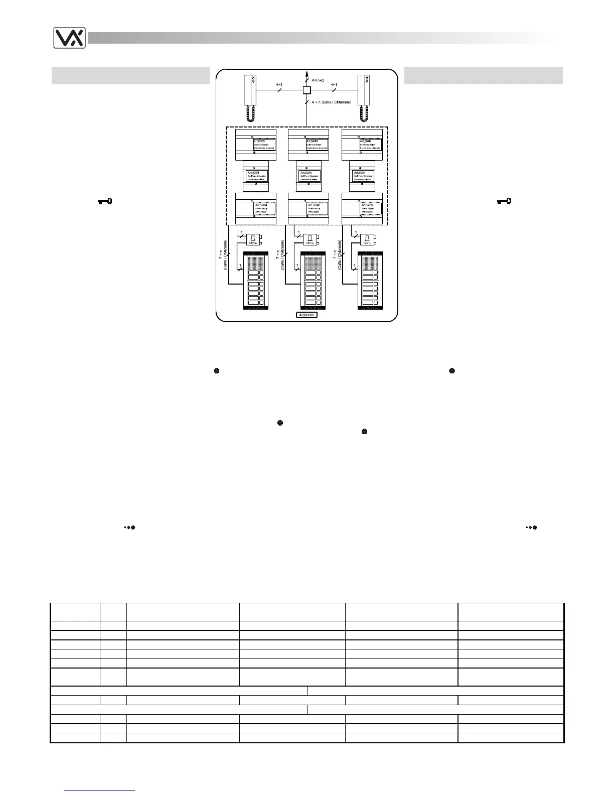
THREE OR MORE ENTRANCES AUDIO
DOOR ENTRY SYSTEM FOR “N” USERS
The system works like the one shown on page
40 but has three or more entrances. A call
from one outdoor station enables the relevant
Art.502N which switches the speech lines and
the “door open service” to the relevant
entrance (position “B”) then sends out the
reset signal on the “R” terminal. Upon
receiving the signal, the other Art.502’s switch
to the “A” position cutting off the speech lines
of the relevant outdoor stations from the main
speech line. Picking up the handset at any
time, the last called user can talk with the
outdoor station and can open the door by
pressing the
push button, relative to the
outdoor station from which the last call is
made.
Installing the system
a. Consult the table below to obtain the
items required. Regarding the number of
modules and the relevant housing (flush
or surface) for them, refer to the section
of this manual relevant to the 800 series
modular system;
b. Run the correct size cables (see page
25). See block diagram for number of
cores;
IMPIANTO CITOFONICO A TRE O PIÙ
INGRESSI PER “N” UTENTI
L’impianto mostrato nello schema funziona
come quello di pagina 40, ma è modificato
rispetto a quest’ultimo per avere 3 o più
ingressi. La chiamata da uno dei posti esterni
porta il relativo scambiatore Art.502N a
commutare in posizione “B” e ad inviare il
segnale di reset sul morsetto “R”: gli altri
scambiatori commutano in posizione “A”
isolando dalla linea fonica i relativi posti
esterni. Solo l’ultimo utente che ha ricevuto
una chiamata e relativamente all’ingresso dal
quale è arrivata, può, sollevando la cornetta,
conversare con il posto esterno ed aprire la
porta premendo il pulsante
.
Realizzazione dell’impianto
a. Consultare la tabella di fondo pagina per
il materiale occorrente: per il numero dei
moduli necessari e per il tipo ed il
numero dei supporti (da incasso o
superficie) da utilizzare per contenerli,
fare riferimento alla sezione, del presente
manuale, relativa al sistema modulare
serie 800;
b. Posare il cavo rispettando le sezioni dei
fili (vedi pag. 25);
c. Test installation (see page 25) and in case of any problem see the
troubleshooting guide of this manual (see page 26).
Extra services and accessories
It is possible to install on the system additional accessories or/and have
extra services by using the service push button
:
1. Installation of an extension sounder (see page 23 fig.2);
2. Installation of a digital codelock module (see page 38 fig.2);
3. Installation of a proximity key reader module to open the door using
proximity keys (see page 38 fig.1);
4. Enable extra services like stair lights or gate opening through an
enslavement relay controlled by the service push button
(see
page 23 fig.6).
c. Eseguire il collaudo dell’impianto (vedi pag. 25) ed in caso di
problemi consultare la ricerca guasti del presente manuale (vedi pag.
26);
Accessori e Servizi Ausiliari
È possibile installare nell’impianto degli accessori aggiuntivi e/o usufruire
di servizi ausiliari utilizzando il pulsante
:
1. Installazione di una suoneria supplementare (vedi pag.23 fig.2);
2. Installazione di un modulo “apri-porta” a codice (vedi pag.38 fig.2);
3. Installazione di un modulo lettore chiavi di prossimità codificate (vedi
pag.38 fig.1);
4. Attivazione di servizi ausiliari come luci scale (o apertura cancello
ecc.) tramite un relè d’asservimento comandato dal
pulsante
(vedi pag.23 fig.6).
Notes
- The intercom is enabled by the incoming call through a link between the
call tone input terminal “T” and the enable input terminal “C”. When a call
is made, the Art.509N temporarily switches off the system to disable all
intercoms and then sends the call tone which enables only the called
intercom to speak and to open the door. The other users of the system
cannot listen to a conversation in progress;
- It is possible to put in parallel a maximum of 4 intercoms for each
extension. In this case, for at least 3 of them, the electronic call tone
volume level must be adjusted to a medium or low level (operating on
the relevant control
) to avoid call tone distortion;
- The same system, with some changes, can be made using intercoms
Art.3123, 3124, 3125 or 3126;
- For each additional entrance a one entrance switch (Art.502N), one
power supply (Art.520M), one call tone generator and speech cut off
circuit (Art.509N), one speaker unit (Art.837-0-1-2) and the push button
modules required. Repeat the connections shown on the diagram for
each entrance.
Note
- I citofoni sono dotati d’ingresso d’abilitazione e sono attivati alla
ricezione della chiamata: all’arrivo della chiamata, l’Art.509N disabilita
tutti i citofoni dell’impianto togliendo temporaneamente l’alimentazione al
posto esterno, quindi emette la nota elettronica che abilita il solo citofono
chiamato a conversare con il posto esterno e ad aprire la porta. Per gli
altri utenti del sistema non è possibile ascoltare una conversazione in
corso;
- È possibile collegare in parallelo al massimo 4 citofoni per ciascun
interno: in tal caso per evitare distorsioni nella nota di chiamata, è
necessario impostare il relativo volume (agendo sul controllo
) ad un
livello medio o basso per almeno tre citofoni.
- Lo stesso impianto, opportunamente adeguato, può essere realizzato
utilizzando citofoni Art.3123, 3124, 3125 o 3126;
- Per ogni ingresso da aggiungere al sistema sono necessari: uno
scambiatore (Art.502N), un generatore di nota elettronica e circuito di
reset (Art.509N), un alimentatore (Art.520M), un portiere elettrico
(Art.837-0, -1 o -2) ed i moduli pulsantiera richiesti. Ripetere i
collegamenti mostrati per gli altri ingressi.
Art.
Qty
Qta
Description Notes Descrizione Note
3121 n
Intercom n = Intercoms in the system
Citofono n = Citofoni nell’impianto
837-0-1-2 3
Speaker unit module
Modulo portiere elettrico
843-4-5 x
Extension front panel module qty depend by extensions
Modulo pulsantiera qta in base al nr. di interni
520M or 520 3
Power Supply Unit
Alimentatore
502N 3
Audio Entrances Switch
Scambiatore d’Ingressi Audio
509N 3
Call tone generator + reset
circuitry
Generatore di nota elettronica e
circuito di reset.
For outdoor station surface mount Per l’installazione da superficie del posto esterno
882-889 x
Surface mounting unit qty depend by nr of modules
Scatola di protezione qta in base al nr. moduli
For outdoor station flush mount Per l’installazione da incasso del posto esterno
852-853 x
Front support qty depend by nr of modules
Supporto frontale qta in base al nr. moduli
862-869 or x
Covering frame qty depend by nr of modules
Cornici di protezione qta in base al nr. moduli
872-879 x
Rainshield qty depend by nr of modules
Tettuccio antipioggia qta in base al nr. moduli
 Loading...