34
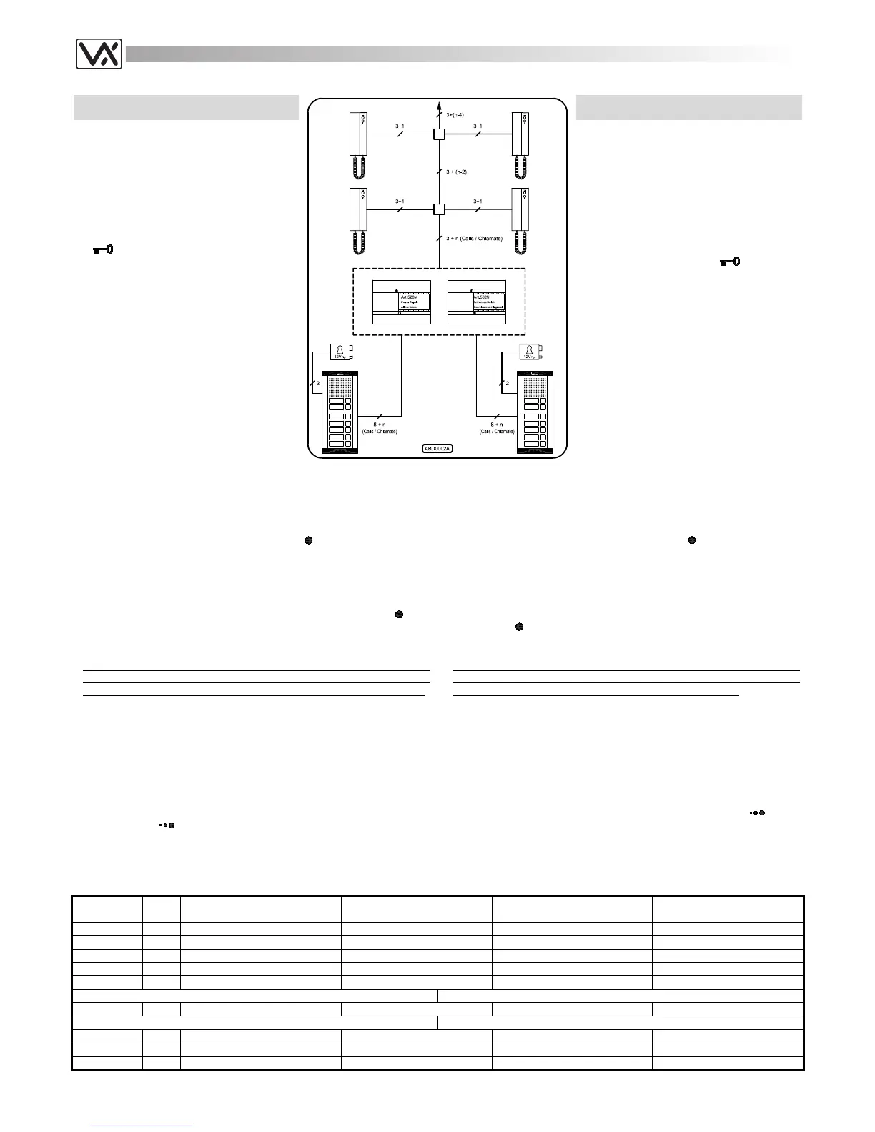
TWO ENTRANCE AUDIO DOOR ENTRY
SYSTEM FOR “N” USERS
The system works like the one shown on page
32 but it has two entrances. The Art.502N
(audio entrances switch) switches the speech
lines and the “door open” service on the
outdoor station from which the last call is
made. Picking up the handset at any time,
each user, relative to the outdoor station from
which the last call is made, can listen to a
conversation in progress or talk with the
outdoor station and open the door by pressing
the
push button.
Installing the system
a. Consult the table below to obtain the
items required. Regarding the number of
modules and the relevant housing (flush
or surface), refer to the section of this
manual relevant to the 800 series
modular system;
b. Run the correct size cables (see page
25). See block diagram for number of
cores;
IMPIANTO CITOFONICO A DUE INGRESSI
PER “N” UTENTI
L’impianto mostrato nello schema funziona
come quello di pagina 32, ma è modificato
rispetto a quest’ultimo per avere 2 ingressi.
L’Art.502N (scambiatore d’ingressi audio)
commuta l’audio ed il servizio di “apertura-
porta” sull’ingresso dal quale proviene la
chiamata. Ciascun utente del sistema
relativamente all’ingresso dal quale è arrivata
l’ultima chiamata, con una conversazione in
corso o l’impianto a riposo, può, sollevando la
cornetta, parlare con il posto esterno ed aprire
la porta premendo il pulsante
.
Realizzazione dell’impianto
a. Consultare la tabella di fondo pagina per
il materiale occorrente: per il numero dei
moduli necessari e per il tipo ed il
numero dei supporti (da incasso o
superficie) da utilizzare per contenerli,
fare riferimento alla sezione, del presente
manuale, relativa al sistema modulare
serie 800;
b. Posare il cavo rispettando le sezioni dei
fili (vedi pag.25);
c. Test installation (see page 25) and in case of any problem see the
troubleshooting guide of this manual (see page 26).
Extra services and accessories
It is possible to install on the system additional accessories or/and have
extra services by using the service push button
:
1. Installation of an extension sounder (see page 23 fig.1);
2. Installation of a digital codelock module (see page 38 fig.2);
3. Installation of a proximity key reader module to open the door using
proximity keys (see page 38 fig.1);
4. Enable extra services like stair lights or gate opening through an
enslavement relay controlled by the service push button
(see
page 23 fig.5 and page 24 fig.9).
c. Eseguire il collaudo dell’impianto (vedi pag.25) ed in caso di problemi
consultare la ricerca guasti del presente manuale (vedi pag.26).
Accessori e Servizi Ausiliari
È possibile installare nell’impianto degli accessori aggiuntivi e/o usufruire
di servizi ausiliari utilizzando il pulsante di servizio
:
1. Installazione di una suoneria supplementare (vedi pag.23 fig.1);
2. Installazione di un modulo “apri-porta” a codice (vedi pag.38 fig.2);
3. Installazione di un modulo lettore chiavi di prossimità codificate (vedi
pag.38 fig.1);
4. Attivazione di servizi ausiliari come luci scale (o apertura cancello
ecc.) tramite un relè d’asservimento comandato dal
pulsante
(vedi pag.23 fig.5 e 24 fig.9).
Notes
- The call tone comes from the ear piece of the handset: to avoid
damage to the hearing, do not leave the handset close to the ear
while the relevant hook switch on the base is down for any reason;
- The “3+1” system allows the speaker unit which incorporates the
enslavement relay to open the electric lock when it receives the door
open signal on terminal “1”. A separate door open wire it is not
necessary when making a link between the terminals “1” and “5” of each
intercom;
- The same system can be made using intercoms Art.3101, 3102 or 3112
without changing the connections;
- It is possible to put in parallel a maximum of 4 intercoms for each
extension. In this case, for at least 3 of them, the electronic call tone
volume level must be adjusted to medium or low level (operating on the
relevant control
) to avoid call tone distortion.
Note
- La nota elettronica è emessa dallo speaker interno alla cornetta:
per evitare danni all’udito, non tenere mai la cornetta accostata
all’orecchio se il relativo gancio sulla base è abbassato;
- L’impianto “3+1” è dovuto al fatto che il posto esterno è dotato del relè di
asservimento per l’apertura della serratura elettrica e può ricevere il
comando “apri-porta” sul morsetto “1”; pertanto il filo per l’apertura porta
viene risparmiato facendo un ponte tra i morsetti “1” e “5” di ciascun
citofono dell’impianto;
- Lo stesso impianto può essere realizzato utilizzando citofoni Art.3101,
3102 o 3112 senza modificare le connessioni;
- È possibile collegare in parallelo al massimo 4 citofoni per ciascun
interno: in tal caso per evitare distorsioni nella nota di chiamata, è
necessario impostare il relativo volume (agendo sul controllo
) ad un
livello medio o basso per almeno tre citofoni.
Art.
Qty
Qta
Description Notes Descrizione Note
3111 n
Intercom n = Intercoms in the system
Citofono n = Citofoni nell’impianto
837M-0-1-2 2
Speaker unit module
Modulo portiere elettrico
843-4-5 x
Extension front panel module qty depend by extensions
Modulo pulsantiera qta in base al nr. di interni
520M 1
Power Supply Unit
Alimentatore
502N 1
Audio Entrances Switch
Scambiatore di Ingressi Audio
For outdoor station surface mount Per l’installazione da superficie del posto esterno
882-889 x
Surface mounting unit qty depend by nr of modules
Scatola di protezione qta in base al nr. moduli
For outdoor station flush mount Per l’installazione da incasso del posto esterno
852-853 x
Front support qty depend by nr of modules
Supporto frontale qta in base al nr. moduli
862-869 or x
Covering frame qty depend by nr of modules
Cornici di protezione qta in base al nr. moduli
872-879 x
Rainshield qty depend by nr of modules
Tettuccio antipioggia qta in base al nr. moduli
 Loading...