Example:
Heat load of the building
²
NW
or Φ
HL buil. W
:
20 kW
DHW demand factor N: 1.3
Heating water flow/return tempera-
ture
– in winter: 110/50 ºC
– in summer: 65/40 ºC
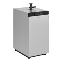
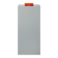
Selected DHW cylinder: 1 Vitocell 300-V
(type EVI), 200 l capacity with
N
L
= 1.4
1. Calculating the required district heating water volume
µ
W
=
District heating water volume in winter in l/h
²
NW
or Φ
HL buil. W
= Connected load in winter in kW
c = Spec. thermal capacity
2. Calculating the connected load in summer with a constant dis-
trict heating water volume (
µ
S
=
µ
W
)
µ
S
= District heating water volume in summer in l/h
²
NS
o Φ
HL buil. S
= Connected load in summer in kW
ΔT
S
= Temperature differential in summer between the
district heating water flow and return temperature in
K
Table 10 – Performance data with return temperature limit
Vitocell 100-V on request.
Vitocell 300-V (type EVI)
Cylinder capacity l 200 300 500
Continuous output at kW 15 16 19
Heating water flow and return temperature 65/40 ºC and
DHW heating from 10 to 45 ºC
l/h 375 393 467
Performance factor N
L
*15
at a heating water flow and return temperature 65/40 ºC and
DHW storage temperature T
cyl
= 50 °ºC
1.4 3.0 6.0
10-minute peak output l 164 230 319
Note
The performance data for DHW cylinders when there is a return tem-
perature limit can be found in the continuous output diagrams in the
relevant datasheets.
Note: When return temperatures are restricted, a check must be car-
ried out to determine whether the hygiene requirements in accordance
with TRWI/DVGW are met. A transfer pump may have to be provi-
ded.
4.2 Sizing according to peak flow rate with reference to DIN 1988-300
For DHW heating systems operating according to the instantaneous
water heater principle, such as e.g. freshwater modules, the DHW
demand can be determined according to the peak flow rate principle.
For this, the assumption is made that the peak flow rate to DIN
1988-300 determined for calculating the pipe dimensions for the DHW
pipework will also have to be heated by the DHW heating system.
The peak flow rate is the sum of all connected individual consumers
(total flow rate), reduced by a simultaneity facto. This is subject to the
type of building.
However, to avoid oversizing, ensure that the calculated peak flow rate
is not higher than the sum of the two largest individual consumers that
may be operating simultaneously. For systems with several independ-
ent consumers, e.g. in apartment buildings, this check will also have
to be carried out with the total flow rate of the respective largest con-
sumer, e.g. of all apartments.
*15
With return temperature limit.
Sizing
(cont.)
20
VIESMANN
DHW heating
4
5414 646 GB