Calculating the DHW demand
This is based on determining the peak flow rate ´
S
to DIN 1988-300.
´
S
= a (Σ ´
R
)
b
- c
(Valid for
´
R
max. = 500 l/s)
´
S
= Peak flow rate
´
R
= Total flow rate (sum of calculation flow rate of all consumers)
a, b, c = Constants subject to building type of use (see table)
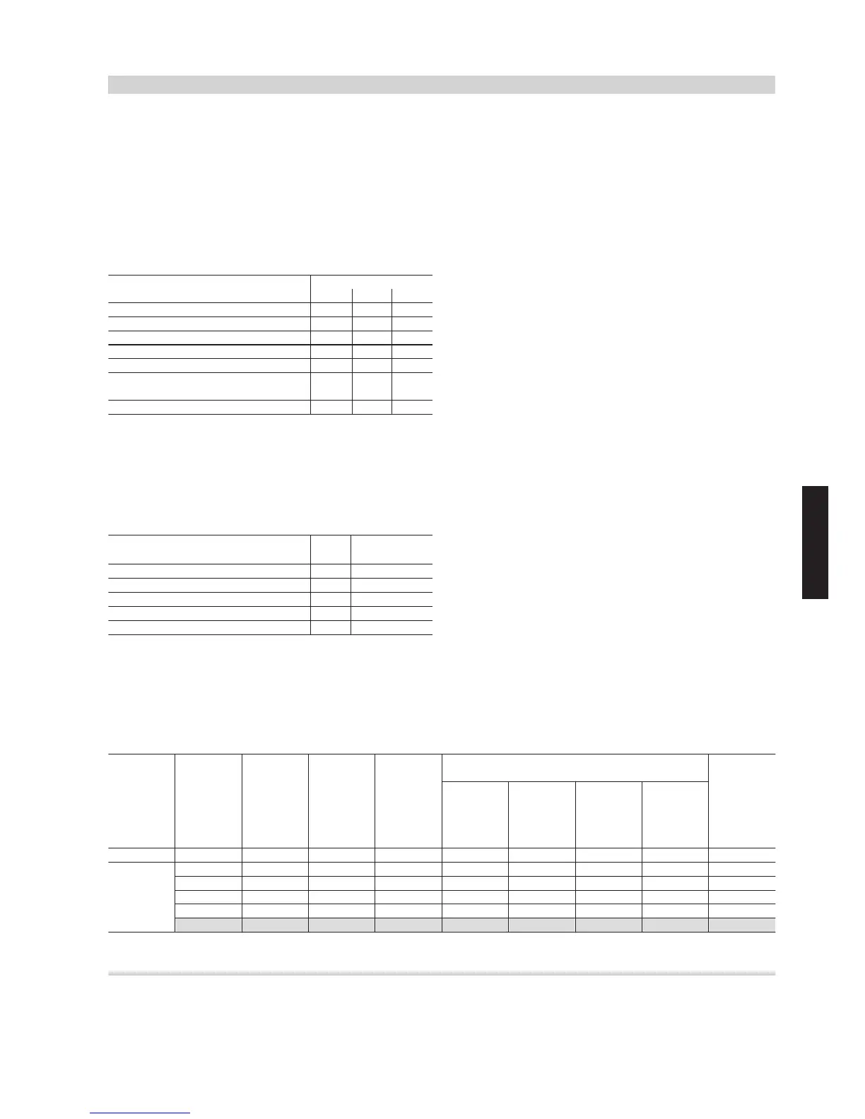
Table 11
Building type Constants
a b c
Residential buildings 1.48 0.19 0.94
Hospital ward 0.75 0.44 0.18
Hotel 0.70 0.48 0.13
School 0.91 0.31 0.38
Administration building 0.91 0.31 0.38
Facility for supported living, retirement
home
1.48 0.19 0.94
Care home 1.40 0.14 0.92
´
R
describes the total flow rate of all consumers. The values of the
DHW calculation flow rate of individual consumers is added to this.
Information on the calculation flow rate are available from the manu-
facturers of the consumers (e.g. tap manufacturers). If they are not
available, the values in DIN 1988-300 can be used:
Table 12 - Calculation flow rate for the connections on the cold
and warm water sides
Mixer taps for type of draw-off point DN Calculation
flow rate
´
R
Shower tray 15 0.15 l/s
Bath 15 0.15 l/s
Kitchen sink 15 0.07 l/s
Washbasin 15 0.07 l/s
Bidet 15 0.07 l/s
Example:
Detached house with 2 bathrooms, 1 kitchen with kitchen sink, 1 guest
toilet with washbasin.
Equipment, bathroom 1: Shower, washbasin
Equipment, bathroom 2: Bath, shower with body showers, 2 washba-
sins
Assuming:
A manufacturer datasheet is available for the shower with body
shower.
The calculation DHW flow rate is: 20 l/min = 0.33 l/s.
Standard values from Table 12 are used for the remaining consum-
ers.
The total flow rate of the detached house is:
´
R
= shower 0.15 l/s + washbasin 0.07 l/s + bath 0.15 l/s + shower
with body shower 0.33 l/s + 2 washbasins 0.07 l/s + kitchen sink
0.07 l/s + washbasin 0.07 l/s
= 0.98 l/s
To calculate the peak flow rate, factors a, b, c for a residential building
are selected from Table 11:
a = 1.48
b = 0.19
c = 0.94
Peak flow rate:
´
S
= a (Σ ´
R
)
b
- c
= 1.48 x 0.98
0.19
– 0.94
= 0.53 l/s
The calculated peak flow rate of 0.53 l/s is greater than the sum of the
two simultaneously operating consumers (shower in bathroom 1 =
0.15 l/s and shower with body shower in bathroom 2 = 0.33 l/s) =
0.48 l/s. Therefore, the value of 0.48 l/s is taken as the peak flow
rate.
The DHW heating system must heat 0.48 l/s = approx. 29 l/min of DHW
from 10 to 60 °C. This results in a transfer rate of approx. 101 kW.
Subject to the heating water temperature or heating water storage
temperature in the heating water buffer cylinder (assumption: 70 °C),
a Vitotrans 353 freshwater module can now be selected from the data-
sheet.
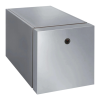
Example: Vitotrans 353, type PZM for installation on a Vitocell 100-E
buffer cylinder (see Table 13).
The values for Vitotrans 353, type PBM (for wall mounting) are the
same as those for the Vitotrans 353, type PZM (for installation on a
cylinder).
Table 13 - Excerpt from "Vitotrans 353" datasheet
Heating wa-
ter tempera-
ture in the
heating wa-
ter buffer
cylinder
Set DHW
tempera-
ture
Max. draw-
off rate
from
Vitotrans
353
Transfer
output
Required
heating
water buf-
fer cylinder
volume per
litre of
DHW
At 10 °C cold water inlet temperature:
Max. draw-off rate at the mixing valve at
Return tem-
perature to
the heating
water buffer
cylinder
40 °C 45 °C 50 °C 55 °C
in °C in °C in l/min in kW in l in l/min in l/min in l/min in l/min in °C
40 65 135 0.5 — — — — 19
45 64 155 0.7 74 — — — 21
70
50 54 149 0.8 71 61 — — 23
55 45 141 0.9 67 57 50 — 26
Ó
60 37 129 1.1 62 53 46 41 31
Calculating the required buffer volume
To provide the energy required for DHW heating, a freshwater module
is normally connected to a heating water buffer cylinder. The heating
water buffer cylinder volume depends on the DHW demand of the
installation, the storage temperature in the heating water buffer cylin-
der and the user behaviour.
The following applies:
V
P
= ´ x t x (T
P
/T
WW
) x s
N
Sizing
(cont.)
DHW heating
VIESMANN
21
5414 646 GB
4