To avoid risk of electrical shock, personal injury, or death, disconnect electrical power source to unit, unless test
procedures require power to be connected. Discharge capacitor through a resistor before attempting to service.
Ensure all ground wires are connected before certifying unit as repaired and/or operational.
WARNING!
Disassembly
©2012 Viking Preferred Service 17
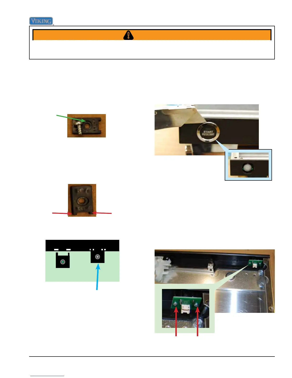
Keeper feet are inserted into
small rectangular holes in the
console, and screwed down
Start Switch Removal
Remove outer door panel, see Outer Door
Removal procedure, Page 15.
Remove the two T10 TORX screws that
mount Start switch to console, see red arrows
below, remove switch.
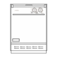
Start Button Removal
Using a very thin object such as the razor
blade shown below, slip under the button collar
and gently lift up until prongs release collar and
button.
When user interface is re-installed care must
be taken to face the four plastic keepers into
the control panel the correct way.
The screw goes into the recessed side of the
keeper, see photo below.
Recessed
side of
keeper
keeper
feet
The plastic keepers have two feet on each
keeper. These feet t into matching slots on
the control panel to ensure that User Interface
Board doesn't move and is rmly anchored.