To avoid risk of electrical shock, personal injury, or death, disconnect electrical power source to unit, unless test
procedures require power to be connected. Discharge capacitor through a resistor before attempting to service.
Ensure all ground wires are connected before certifying unit as repaired and/or operational.
WARNING!
Troubleshooting
©2012 Viking Preferred Service 35
Component
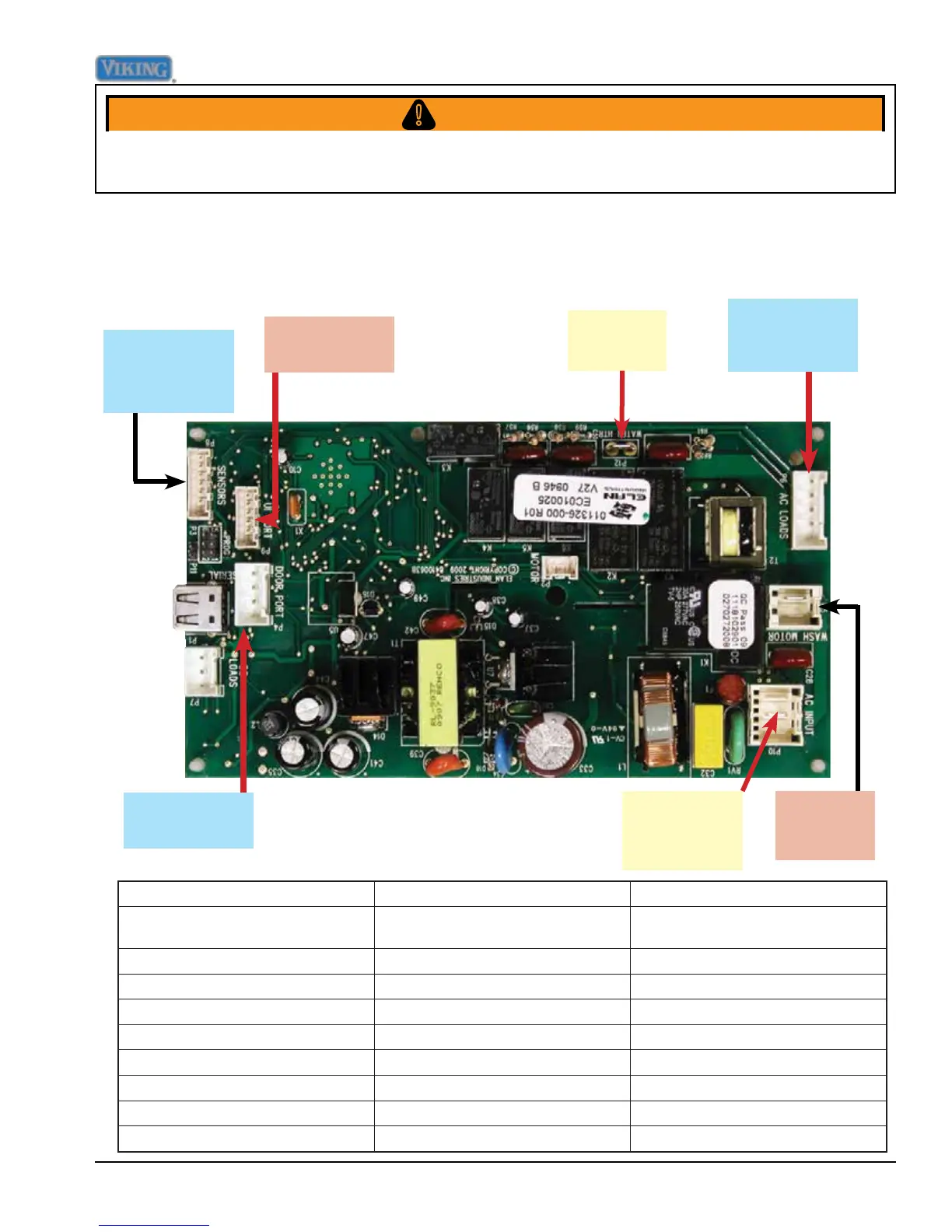
Control Board Test
Point
Readings
(
T
ypical)
Door Switch P4-1 (Yellow) – P4-2 (RD/WH)
0 Ω door closed
∞
Ω door
open
Dispenser P4-1 – P4-4
8.3 Ω
Wash
Motor
P5-1
(Red)
– P5-2 (White)
6.3 Ω
Water Valve P6-3
(Blue)
– P10-1 (White)
1.1K Ω
Drain Pump P6-4 (Brown) – P10-1 (White)
15.1 Ω
Diverter P6-2
(Gray)
– P10-1 (White)
2.7K Ω
Moisture Sensor P8-1 (Red/White) – P8-2 (Purple)
175K Ω
Temperature Sensor P8-3 (Black/White) – P8-4 (Blue)
47K Ω @ 77˚
(varies
based on temp)
Water Heater P12
(Gray)
– P10-1 (White)
12.00 Ω
P8 Moisture
sensor / Tem-
perature sensor
P9 User Inter-
face Port
P12 Water
Heater
P6 Water valve,
Drain pump,
Diverter
P5
Circulation
Motor
P10
Water valve,
Drain pump
P4 Door switch,
Dispenser
The unit has a control board that controls the functions of the dishwasher. Components can be
diagnosed via the control board. With the control board accessed (see Control Board Disassem-
bly procedure, Page 31), the following can be measured:
Control Board Test Points