© 2011 Viking Preferred Service
25
Service Diagnostics and Procedures
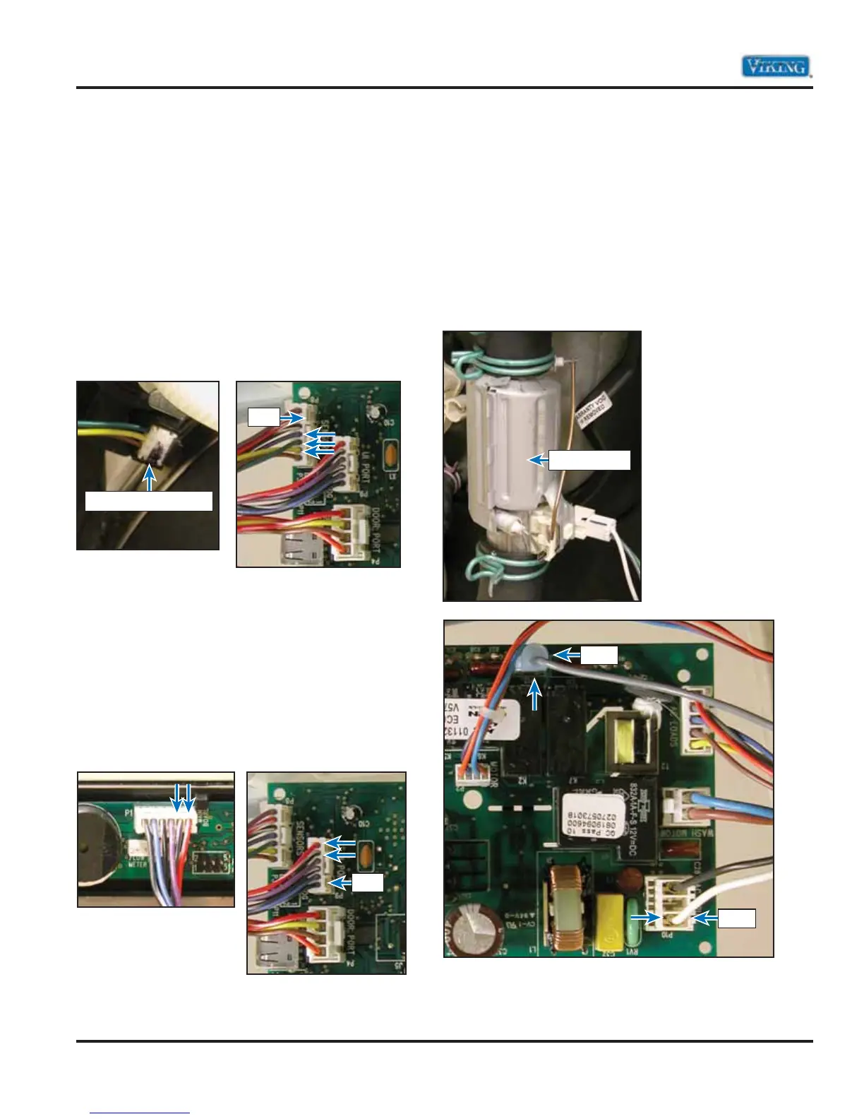
Washer Pressure Sensor
The sensor is mounted to the sump retainer ring.
As the water level increases, the pressure in the 1
pressure tube, connected to the level sensor input,
increases as well. This pressure causes an internal
amplifier to vary the output voltage to the board.
Forexample, an empty sump should produce a
reading of .5 -.8 Volts DC between P8-6 (yellow)
and P8-5 (ground) while a full sump should read
approximately 3.5 volts DC. Depending on the
water level, the output voltage to the Control Board
changes and is processed in the board.
User Interface Port
The user interface allows the end consumer to make
cycle selections. As the selection is made, the signal
is sent to the control board via a ribbon connection.
Voltage between P9-1 and P9-2 should be 12 VDC.
If no voltage is found, check ribbon connector. If
connector is OK, replacement of the user interface
is necessary (see Control Panel Removal procedure,
page 30).
Water Heater
The unit uses a 120-volt, 1200 watt heater to heat
the water during the wash cycle. To check the
heater, unplug the gray wire on P12 and using an
ohmmeter, check for 12 ї ohms between the gray
wire and Neutral. If 0 їohms are read, check the
wiring to the heater. If the wiring is correct, replace
the heater. The heater can also be tested in the
Diagnostic mode (see pages 14-15).
Control Board Diagnosis (continued)
(
Some measurements require power and others require the unit not to be powered.)
Water Pressure Sensor
P-8
Main Control Board
P-9
Main Control Board
User Interface Board
P-10
P-12
Water Heater
Main Control Board