© 2011 Viking Preferred Service
52
Service Diagnostics and Procedures
Dryer Motor–450 model (cont.)
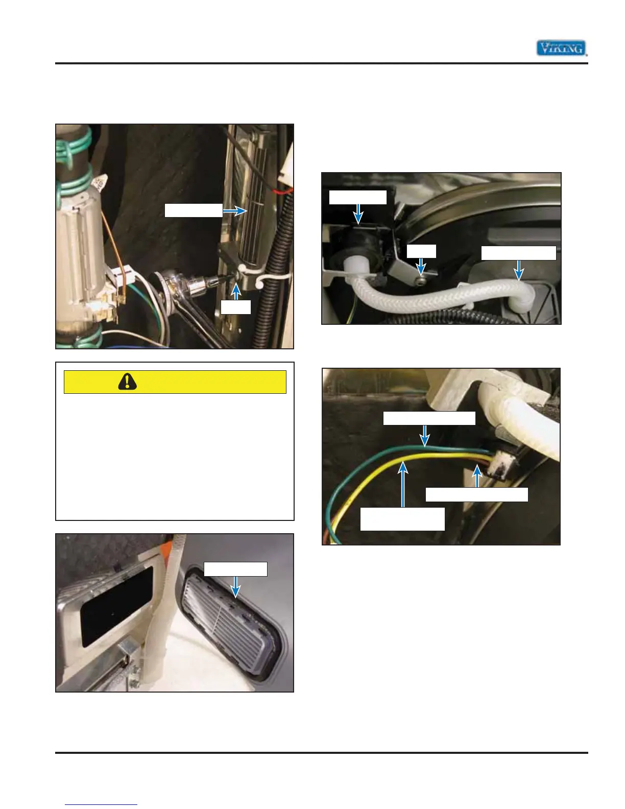
Remove the inner T-20 TORX® screw.
Water Level Sensor
The level sensor is mounted to the sump retainer
ring with a T-25 TORX® screw. Removing the level
sensor DOES NOT require the removal of the
dishwasher from the cabinet. With the toe kick
removed, locate the level sensor shown below.
The image below shows the three wire connector to
the level sensor.
As the water level increases, the pressure in the
1/4” (.63 cm) pressure tube, connected to the level
sensor input, increases as well. This pressure causes
an internal amplifier to vary the output voltage
to the board. An empty sump should produce a
reading of .5 - .8 VDC between J9 – 4 and ground
while a full sump should read approximately 3.5
VDC. Depending on the water level, the output
voltage to the control board changes and is
processed in the board.
Dryer Blower
Screw
CAUTION
When reinstalling the air/water inlet assembly,
make sure that both the front and rear brackets
are snapped back into their proper positions
Failure to do so may cause water to leak
through and then onto the consumer’s floor.
The O-ring gasket MUST be undamaged
(shown below) or water can leak out of the
unit and cause damage to the unit and the
kitchen area.
O-Ring Gasket
Level Sensor
Screw
Sump Connection
Brown Wire 5 volts DC in
Green WIre Ground In
Yellow Wire
0.5-3.5 volts DC out