© 2011 Viking Preferred Service
40
Service Diagnostics and Procedures
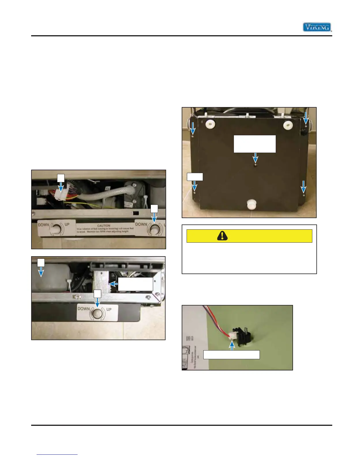
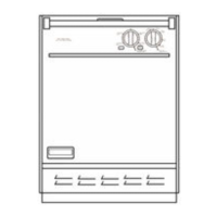
Base Pan–Front View
With the dishwasher lying on its back and the toe
kick removed, you can look into the base assembly
sand check several points before requiring the
removal of the unit for service.
In the images below, you can see the sump
assembly (1),12-Pin disconnect pin (2), and the rear
leveling leg adjustment screw (3). In order to access
and service the remaining components, the base
cover will need to be removed to gain access. This
includes the drain motor, circulation motor, control
board, flow-through water heater, wash temp
sensor, water valve, front levelers, and the rear
leveler (motor controller, dryer heater and dryer
motor on the 450 model).
Base Cover Disassembly
Remove the four T20 TORX® screws that hold the
bottom base to the dishwasher superstructure. The
image below shows the location of these screws.
With the panel removed, locate the moisture sensor
and unplug, leaving the moisture sensor attached
to the base pan.
The image below shows the moisture sensor
secured to base pan. The sensor is secured in place
by one T15 TORX® screw (shown above).
Note: Place base pan in a secured area. Take care
not to damage the sensor.
With the base pan removed, you now have access
to locate, diagnose, and service all the components
in the base of the dishwasher.
(2)
(3)
Water
Overflow tube
(1)
(3)
Screw
T15 TORX® screw
securing moisture
sensor to base pan
Unplug connector here
CAUTION
After the four screws that secure the pan to
the frame are removed, be careful because the
moisture sensor is mounted to the pan and the
wiring could be damaged.