© 2011 Viking Preferred Service
33
Service Diagnostics and Procedures
Door Disassembly (cont.)
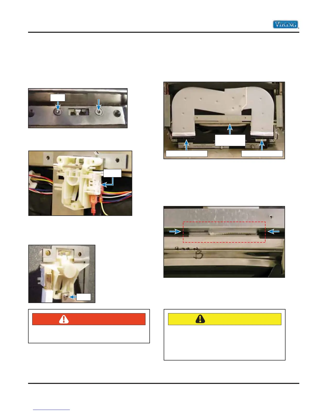
Door Latch Interlock
The door latch mechanism is secured to the inner
door panel by two T20 TORX® 3/4” (1.9 cm)
screws. With the control panel removed, remove
the two screws.
Remove the latch mechanism and unplug the 2-wire
connector plug from the micro switch shown below.
If replacing the switch, remove the bracket from the
old switch and reinstall on the replacement latch
assembly. Remove the TORX® screw shown below.
Inner Door Duct Assembly–450 model
The image below shows the lower section of the
vent assembly, including the air discharge and
moisture return outlet.
The moisture return outlet of drying vent assembly
is held in a retaining bracket which is secured to
the inner door liner. In order to remove from the
bracket, first grasp onto the vent, carefully bend the
bracket (over bending will create a leak), and pull
the duct.
The two arrows above show the vent in position.
The rectangular red lines shows the area where the
condensed moisture returns to the sump area.
12 VDC
Screw
Screw
DANGER
Failure to observe caution could result in electric
shock, resulting in permanent injury or DEATH.
Dryer Air Dishcarge Dryer Air Dishcarge
Moisture
Return Outlet
CAUTION
Make sure that when the vent is reinstalled that
the moisture return outlet is snapped back
properly into the bracket. Failure to do so may
cause water to leak onto the consumer’s floor.