© 2011 Viking Preferred Service
51
Service Diagnostics and Procedures
Heater Assembly–450 model (cont.)
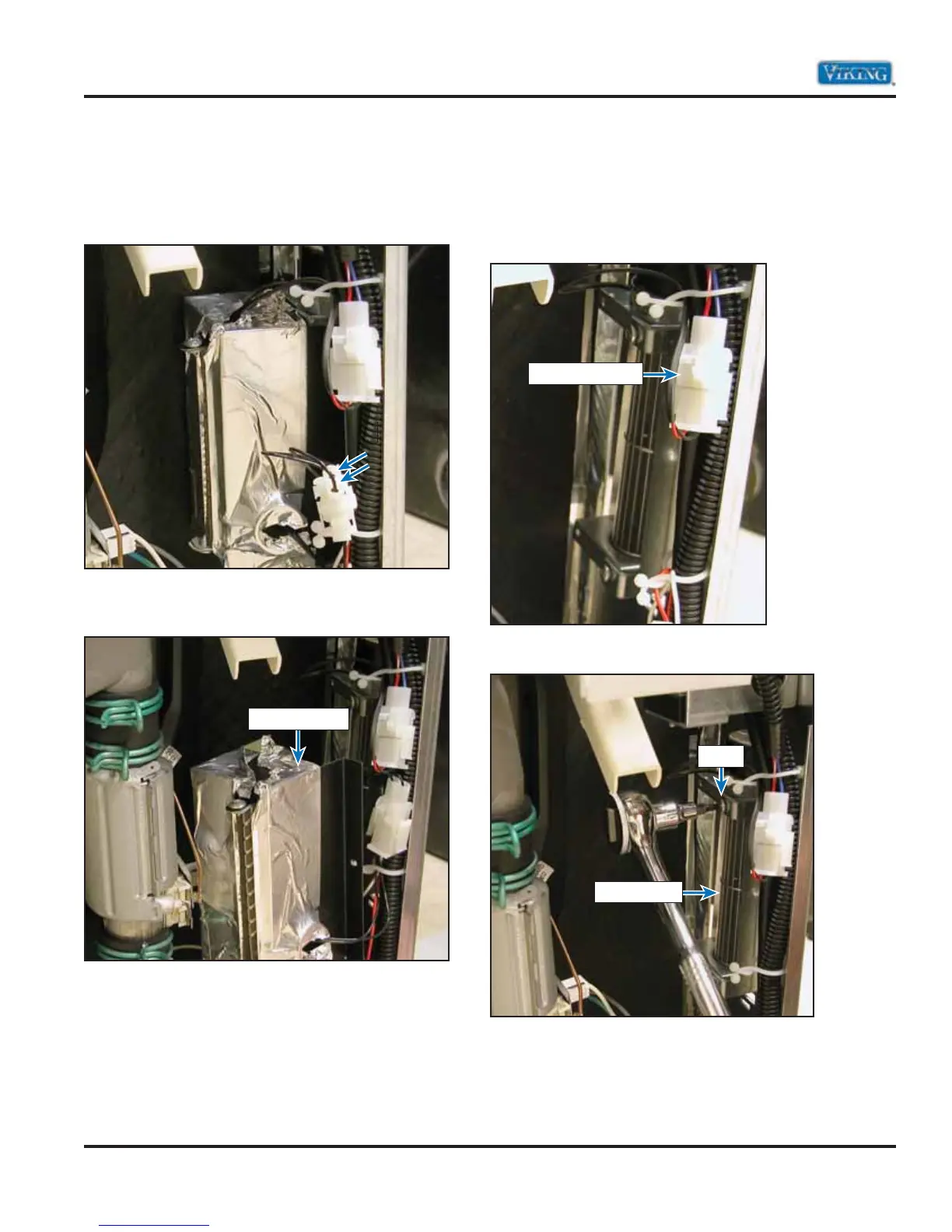
The image below shows the complete heater
housing. The two black wires in the photo go to the
120 drying heater. The power is sent from the P6-1
(orange) on the control board.
Remove the heater housing to expose the blower
motor.
Note: When reassembling the heater housing, you
must replace the aluminum tape that was removed
during disassembly. Failure to do so may cause
improper air flow across the heater.
Dryer Motor–450 model
With the dryer heating element removed you now
have access to the dryer blower motor. Remove the
2-wire connector shown below. The blue (P7-3) and
red with white tracer (P7-1) supply 12 volts to the
dryer motor.
Remove the outer T-20 TORX® screw shown below.
Heater Housing
2-Wire Connector
Dryer Blower
Screw