© 2011 Viking Preferred Service
50
Service Diagnostics and Procedures
Dryer Motor and
Heater Assembly–450 model (cont.)
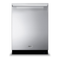
With the tape cut and removed, locate the front
and rear T20 TORX® screws that hold the heater
assembly in place,(shown already removed below).
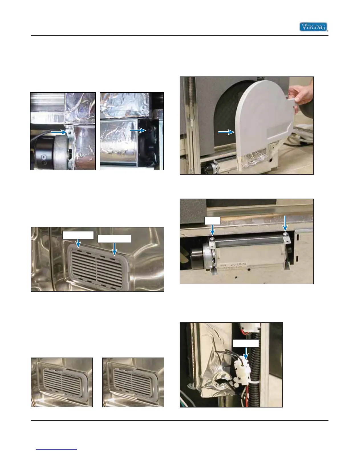
To access the remaining two screws, the right side
air/water Inlet assembly will need to be removed.
Open the dishwasher door to locate the air/water
Inlet assembly. This assembly is held in place by a
front and rear locking bracket. The image below
shows the inlet with both brackets attached.
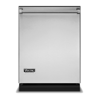
Using a flat blade screwdriver, gently pry the
locking brackets off the inlet assembly. Both the
front and rear brackets are the same. The rear
bracket must slide backwards to remove and the
front bracket slid forward to remove.
The images below shows the rear bracket removed
(left) and front bracket removed (right).
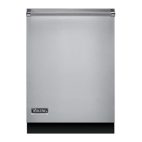
With the locking brackets removed, pull the fill
chamber away from the right side of the unit.
Remove the two remaining TORX® screws that are
indicated below. Now remove the heater assembly.
Note: In the image above, the air/water Inlet
assembly is detached from the machine.
Disconnect the connector to the heater.
Rear Bracket
Front Bracket
Screw
Connector