© 2011 Viking Preferred Service
58
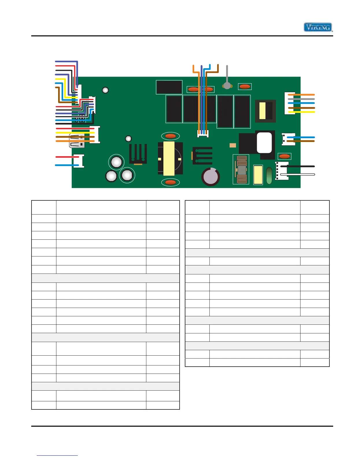
Wiring and Schematics
Control Board Wiring Connections
Pin
Number
Description
Wire
Color
P8-1 Moisture sensor Purple
P8-2 Moisture sensor Red/White
P8-3 Temperature sensor Black/White
P8-4 Temperature sensor Blue
P8-5 Pressure sensor–ground Green
P8-6 Pressure Sensor–.5 to 3.5 volts input Yellow
P8-7
Pressure Sensor–5 volts iutput
Brown
P9-1 User interface Red/White
P9-2 User interface Black/White
P9-3 User interface Purple
P9-4 User interface Black/White
P9-5 User Interface Blue
P9-6 User interface Black/White
P4-1 Common to door switch, detergent
dispenser and wax motor (450 series)
Red/White
P4-2 Door switch Yellow
P4-3 Vent Motor
(450 series)
Brown
P4-4 Dispenser Orange
P7-1
Drying motor–12 volts (450 series)
Red/White
P7-2
Drying motor–12 volts (450 series)
Blue
Pin
Number
Description
Wire
Color
P2-1 5 volts DC to motor controller Brown
P2-2 Serial send to motor controller Blue
P2-3 Ground from motor controller Purple
P2-4 Serial receive from motor controller Orange
P12 Water heater Gray
P6-1 Drying heater (450 series) Orange
P6-2 Diverter–motor Gray
P6-3 Water valve Blue
P6-4 Drain motor Brown
P6-5 Diverter–switch Yellow
P5-1 Neutral to motor controller board Blue
P5-2 120 volts to motor controller board Brown
P10-1 Line in Black
P10-2 Neutral White
WATER HTR
DC
LOADS
DOOR PORT
SENSORS
PROG
P3 P1
P1
P7
P4
P9
P8
UI PORT
P4
K7 K2
K6
P2
P12
P10
WASH MOTOR
K5
K4
MOTOR
P5
P6 AC LOADS
P2-1 P2-2 P2-3 P2-4
P12
P6-1
P6-2
P6-3
P6-4
P6-5
P5-1
P5-2
P10-1
P10-2
P4-1
P4-2
P4-3
P4-4
P7-1
P7-2
P8-1
P8-2
P8-3
P8-4
P8-5
P8-6
P8-7
P9-1
P9-2
P9-3
P9-4
P9-5
P9-6