Troubleshooting
©2013 Viking Preferred Service 23
To avoid risk of electrical shock, personal injury, or death, disconnect electrical power source to unit, unless test
procedures require power to be connected. Discharge capacitor through a resistor before attempting to service.
Ensure all ground wires are connected before certifying unit as repaired and/or operational.
RTD Sensor
Proper diagnostics of the RTD (Resistance Temperature
Detector) will eliminate unnecessary replacement.
The RTD is designed to change resistance as the
temperature in the oven cavity changes. As the
temperature increases, so does the resistance. At 75°F,
the resistance should be approximately 1090 ohms.
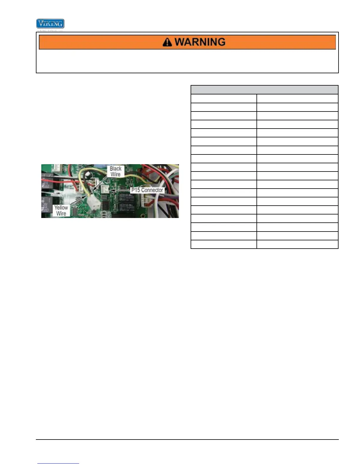
Locate the P15 connector on control board. The P15
connector will have a Molex plug containing a yellow and
black wire. The yellow and black wires go to the oven
sensor.
With the Molex plug removed, use an ohmeter to
measure resistance between the yellow and black
wires in the Molex connector. At ambient temperature,
you should read around 1090 ohms (±10%). An open
reading (∞) indicates either a broken wire or an open
RTD. Finally, test each wire to ground to check for a
pinched wire to the oven frame. If wiring is OK, replace
the sensor.
If the RTD resistance is within the specifications given,
it is not necessary to replace the RTD. If the RTD test
resistance is within specifications and the consumer
is having erratic oven temperatures, please call Viking
Technical support (1-800-914-4799) for assistance.
RTD Characteristics
RTD (Resistance Temperature Detector)
Temperature (°F)
Approximate Resistance (
W)
50 1038
75 1090
100 1143
200 1350
300 1553
350 1654
400 1754
450 1852
500 1950
550 2047
600 2153
650 2238
700 2332
750 2425
800 2518
850 2609
900 2700
NOTE: Door switch must be depressed in order for
the convection fan and all convection cycles,
Auto Roast and Dehydrate heating elements to
operate when the door is opened.