Disassembly
38 ©2013 Viking Preferred Service
To avoid risk of electrical shock, personal injury, or death, disconnect electrical power source to unit, unless test
procedures require power to be connected. Discharge capacitor through a resistor before attempting to service.
Ensure all ground wires are connected before certifying unit as repaired and/or operational.
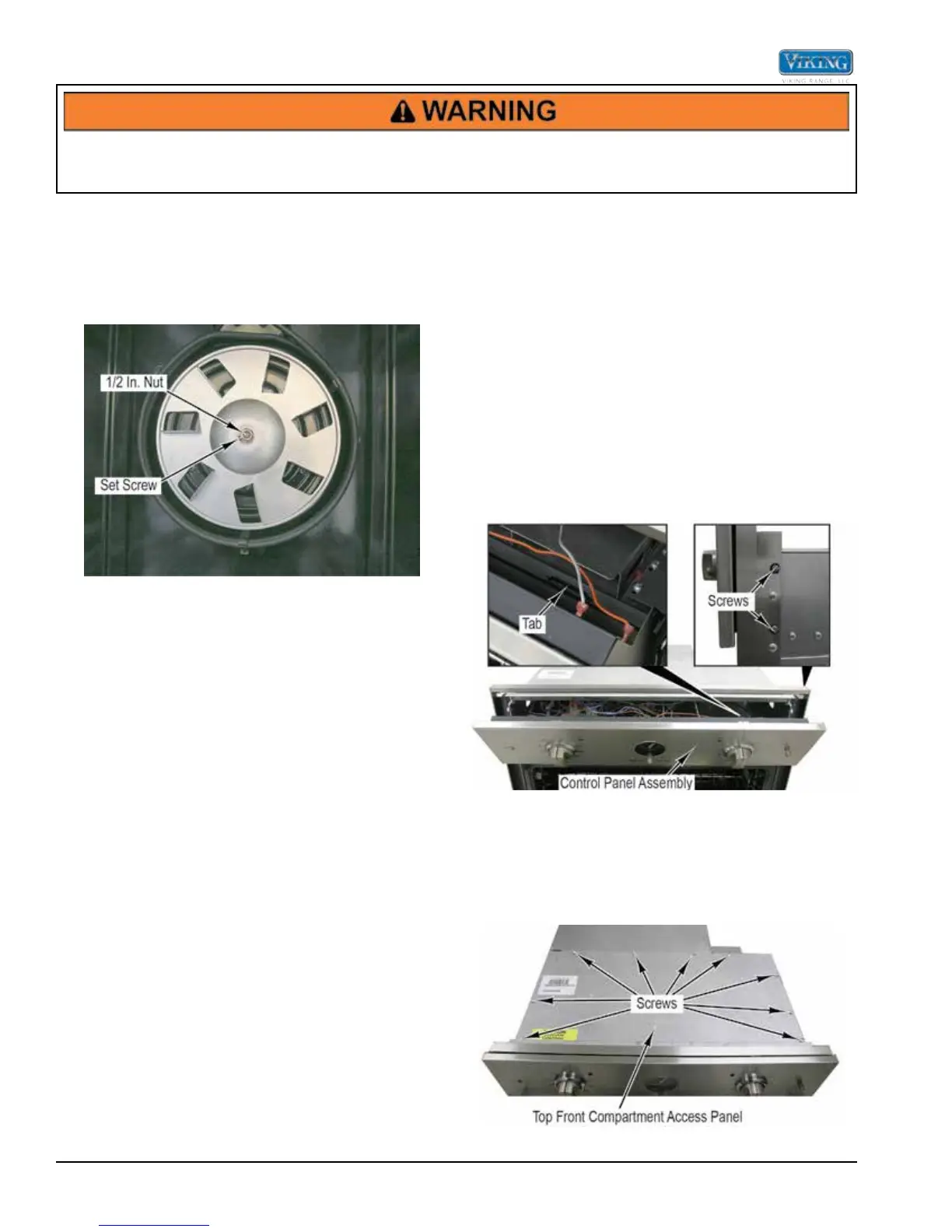
Convection Fan Blade Removal
1. Remove convection baffle (see Convection Baffle
Removal).
2. Loosen the fan setscrew counterclockwise two to
three turns.
3. Remove the 1/2-inch nut from the fan.
4. Lift the fan blade from the fan motor shaft.
NOTE: Upon reassembly, tighten the 1/2-inch fan nut
BEFORE tightening setscrew to the at surface
on the fan motor shaft.
5. Reverse procedure for installation.
Access to Control Components
The control components are located on top of the
oven. Access is required in order to perform many
troubleshooting procedures and remove some control
components. The single and double ovens are similar.
The upper oven controls are on the left side and the
lower oven controls are on the right. Partial or complete
access may be required depending on the component
being tested or removed.
Control Panel Access
1. Partially remove the oven from the installation (see
Partial Oven Removal).
2. Remove two screws from each side of the oven that
secure the control panel assembly to the oven.
3. Lower the control panel assembly forward leaving the
panel in the three tabs along the bottom of the panel.
4. Reverse procedure for installation.
Partial Control Board Area Access
1. Partially remove the oven from the installation (see
Partial Oven Removal).
2. Remove nine screws and the top front component
access panel.
3. Reverse procedure for installation.