Chapter 3 Analog output modules Manual VIPA System 200V
3-18 HB97E - SM-AIO - Rev. 12/32
6Byte of parameter data are available for the configuration data. These
parameters are stored in non-volatile memory and are available after the
unit has been powered off.
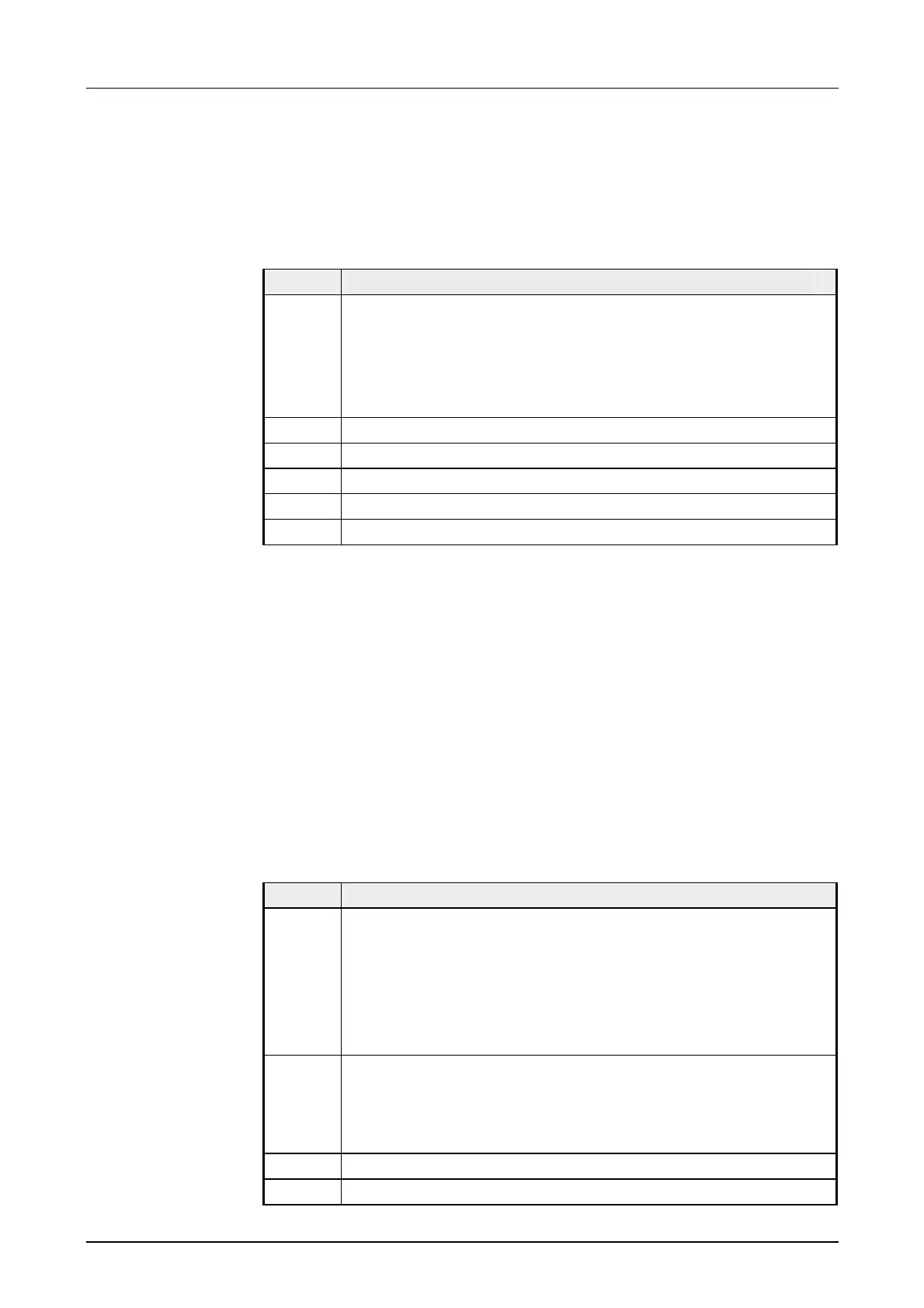
The following table shows the structure of the parameter data:
Parameter area:
Byte Bit 7 ... Bit 0
0 Diagnostic interrupt byte:
Bit 5 ... 0: reserved
Bit 6: 0: diagnostic interrupt inhibited
1: diagnostic interrupt enabled
Bit 7: reserved
1 reserved
2 Function-no. channel 0
3 Function-no. channel 1
4 Function-no. channel 2
5 Function-no. channel 3
Diagnostic interrupt
You can enable diagnostic interrupts by means of bit 6 of byte 0. When an
error occurs 4 diagnostic bytes are transmitted to the master system.
Function-no.
Here you enter the function-no. of the output function for every channel.
The relationship between the function number and the output functions is
available from the function-no. allocation table.
When you enable alarms in byte 0 of the parameter area, modules will
transfer 4 diagnostic bytes with pre-defined contents to your master in case
of an error. Please note that analog modules only use the first two bytes for
diagnostic purposes. The remaining bytes are not used.
The structure of the diagnostic bytes is as follows:
Diagnostic data:
Byte Bit 7 ... Bit 0
0 Bit 0: Module malfunction
Bit 1: reserved
Bit 2: External error
Bit 3: Channel error present (wire break/short circuit)
Bit 6 ... 4: reserved
Bit 7: Wrong parameter at module
1 Bit 3 ... 0: class of module
0101 analog module
Bit 4: channel information available
Bit 7 ... 5: reserved
2 not assigned
3 not assigned
Parameter data
Parameter
Diagnostic data