Manual VIPA System 200V Chapter 2 Analog input modules
HB97E - SM-AIO - Rev. 12/32 2-21
During a measurement the data is stored in the data input area.
The following figure shows the structure of the data input area:
Data input area:
Byte Bit 7 ... Bit 0
0 High-Byte channel 0
1 Low-Byte channel 0
2 High-Byte channel 1
3 Low-Byte channel 1
4 High-Byte channel 2
5 Low-Byte channel 2
6 High-Byte channel 3
7 Low-Byte channel 3
Note!
Only channels 0 and 2 are used in 4wire systems.
When using Thermocouples the diagnosis for wire break is always active. If
a diagnosis alarm is parameterized, the module initializes a diagnosis at
wire break for the corresponding channel.
Every channel is individual parameterizable. For the parameterization,
10byte parameterization data are available. The parameterization data are
stored permanently and remain also in off mode. By using the SFC 55
"WR_PARM" you may alter the parameterization in the module during
runtime. The time needed until the new parameterization is valid can last up
to 60ms. During this time, the measuring value output is 7FFFh.
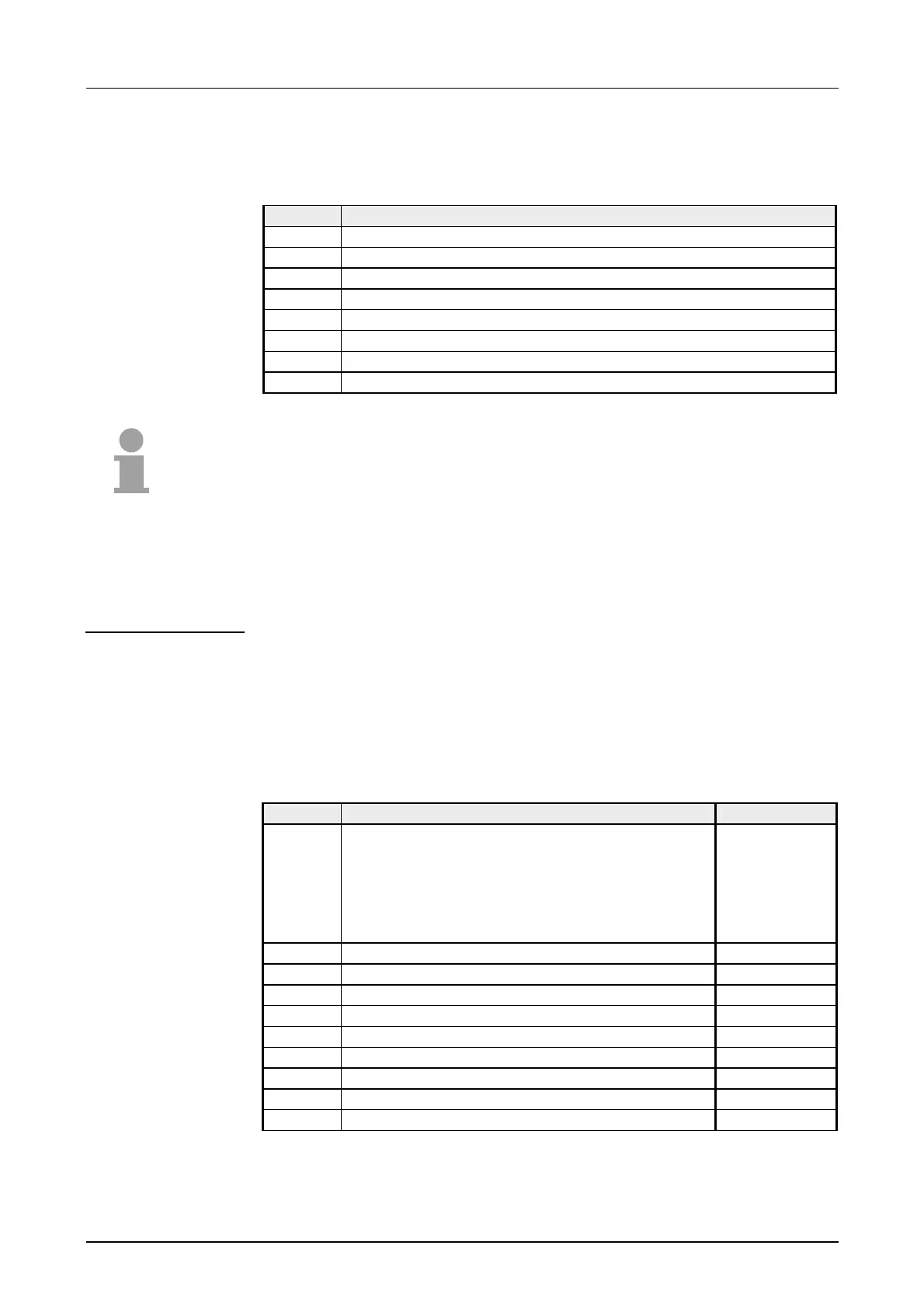
The following table shows the structure of the parameter data:
Parameter area:
Byte Bit 7 ... Bit 0 Default
0 diagnostic:
Bit 5 ... 0: reserved
Bit 6: diagnostic interrupt
0: deactivated
1: activated
Bit 7: reserved
00h
1 Bit 7 ... 0: reserved 00h
2 Function-no. channel 0 28h
3 Function-no. channel 1 28h
4 Function-no. channel 2 28h
5 Function-no. channel 3 28h
6 Option-Byte channel 0 00h
7 Option-Byte channel 1 00h
8 Option-Byte channel 2 00h
9 Option-Byte channel 3 00h
Measurement data
acquisition
Diagnosis at wire
break with
Thermocouples always
active
Parameter data