EasyManua.ls Logo

Vislink Microlite 3 - Connector Details; Power and Serial Port Connections

Vislink Microlite 3
49 pages
Print Icon
To Next Page IconTo Next Page
To Previous Page IconTo Previous Page
Loading...
Operators Manual
Installation
M55-ML3-UG, Rev A
19
Table 3: MLT3 Connectors
Reference
Name
Description
Physical Type
Placement
1
RF Output/
COFDM Output
SMA Female #1
Top of Unit
2
Telemetry
Telemetry
Input/output
SMA Female #2
Top of Unit
3
Video In #1
SDI
DIN
Bottom of unit
4
Video In #2
HDMI
HDMI
Bottom of unit
5
Power In # 1
6.5-28VDC
Lemo 7 pin
Bottom
3 & 4
Audio In
Embedded in SDI
DIN
Bottom of unit
5
User Data In
RS232
Lemo 7 pin
Bottom of unit
5
Camera
Control Data
External control data
Lemo 7 pin
Bottom of unit
6
Wi-Fi
Remote Control
Embedded
Antenna
Embedded
7
Software
USB
Micro USB
Bottom of unit
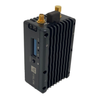
7.4.2. Power Serial Port Connections (Item 5)
Item 5 is a 7-pin Lemo connector that provides connectivity for the following:
Power Input (6.5-28VDC)
RS232
RS422/485
S-Bus
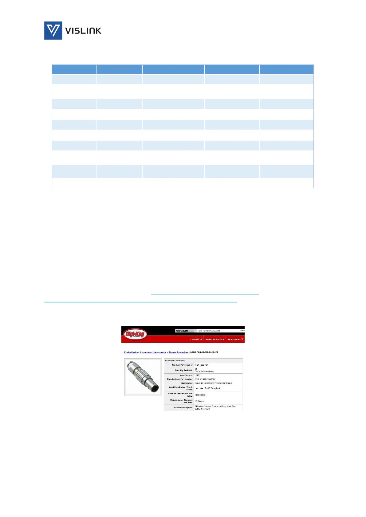
Lemo connector mating part link: https://www.digikey.com/product-
detail/en/lemo/FGG.0B.307.CLAD52Z/1124-1060-ND/2786162
Figure 4: Power and Serial Lemo Mating Connector

Table of Contents