7.4.3. Antenna Connection
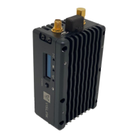
Connect antenna to RF Output (Reference 1). There are three different mounting models
of the MLT3 with different RF output connectors:
• Standard (Hotshoe) SMA
• Clamshell N-Male
• L-Bracket SMA
7.4.4. Connecting Power
The Microlite 3 operating voltage with 6-28VDC. The MLT3 kit includes 2 power cable
options:
1. Lemo to D-Tap for connecting to a battery or camera. (Item 8 in the accessory kit)
2. Lemo to the bare tinned wire for application-specific or OEM installation. (Item 9 in the
accessory kit.