Operators Manual
Operation
M55-ML3-UG, Rev A
22
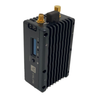
The Local User Interface in Figure 6 indicates the following:
• Channel 2; 5740.0MHz
• 8MHz
• High Power
• DVB-T Modulation
• LED Indicators
• Power ON
• Video input good
• Transmitting
Figure 6: Green LED indicators and OLED Display
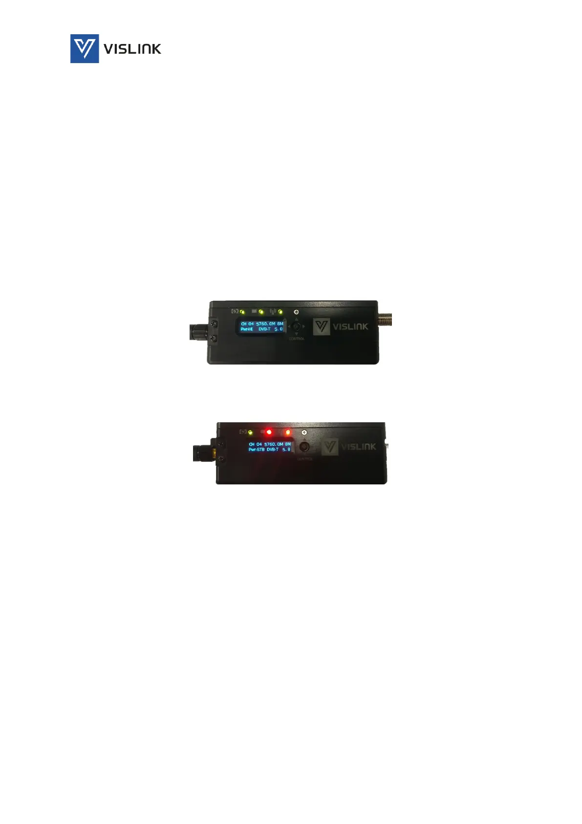
Figure 7: No Video Input Sensed and RF is on Standby
8.2. Using the Local User Interface to Control the Microlite 3
The MLT3 local user interface displays the following:
• Channel and Frequency
• Bandwidth
• Power State
• Modulation Type
• Band (optional)
Only 3 of the parameters may be changed via the front panel joystick (see wireframe below):
• Channel
• Power State
• Band (optional)