Operators Manual
Operation
M55-ML3-UG, Rev A
37
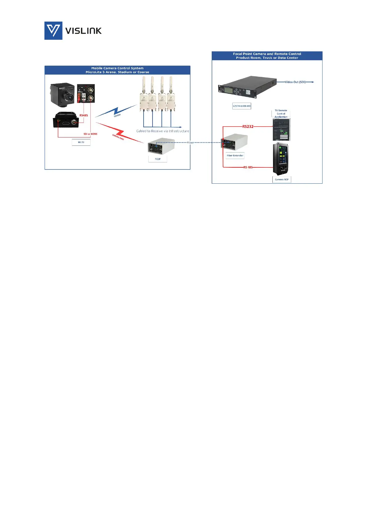
Figure 27: MLT3 Camera Control with Fiber Extension
8.5.4. Operation
1) Connect as shown in Figure 26, Figure 27, or as solution drawing provided by
Vislink.
2) Install the Vislink Remote Control (VRC) application onto a laptop from the USB
stick. Connect Laptop or Device to the serial input of the FCDT using the Serial
Cable and the Rs232 USB-DB9 Dongle.
3) Connect the RS485 DB9 connector end of the above cable to RCP.
4) Connect the MLT3 Power/Serial Cable to both the power source and the RS485
input/output of the camera.
5) Power on all units.
6) Open the application and enter the MLT3 Transmitters name (serial number) and
channel into the application.
a. The VRC may control up to 5 MicroLite’s at a time.
b. The MicroLite’s must be set to an individual telemetry channel using the Wi-Fi
control application.
c. The Microlite has been pre-programmed with telemetry channels.
d. Enter each MicroLite transmitter by pressing the ‘Add Transmitter’ button and
entering a name or serial number plus picking the channel from the dropdown list.
Since the DFs have been pre-programmed, enter as shown in Figure 28.