EasyManua.ls Logo

Vislink Microlite 3 - Microlite 3 Connectors; Figure 25: MLT3 Connectors; Table 6: MLT3 Camera Control Kit; Table 7: MLT3 Connectors

Vislink Microlite 3
49 pages
Print Icon
To Next Page IconTo Next Page
To Previous Page IconTo Previous Page
Loading...
Operators Manual
Operation
M55-ML3-UG, Rev A
35
Table 6: MLT3 Camera Control Kit
Item No
Component Part
Part Description
Qty
1
FCDT-ASSY-7123
Focal Point Outdoor Unit SC/UPC 410-490MHz/900MHz
(Dual Serial)
1
2
FCDT-ASSY-7124
Focal Point Outdoor Unit SC Serial to Fiber Connector
1
2
FCDT-ASSY-2101
Focal Point Serial Cable - 5 pin XLR to DB9 Female(RS232)
and DB9 (RS485)
1
3
922-B982-01A-R
CABLE USB RS232 EMBED 10CM LED;FTDI US232R-10-
BULK
1
4
922-B1061-01B-R
Power Supply - AC to 12VDC
1
5
9017156
Antenna with mounting L-COM 903-928MHZ 3dBi antenna
1
6
9013335
Cable - FCDF to Antenna - LMR-400 10ft
1
7
USB Stick
USB stick with RC application and user guide
1
8
MLT3-ASSY-2101
Power/Serial Cable - 7 Pin Lemo to Breakout
1
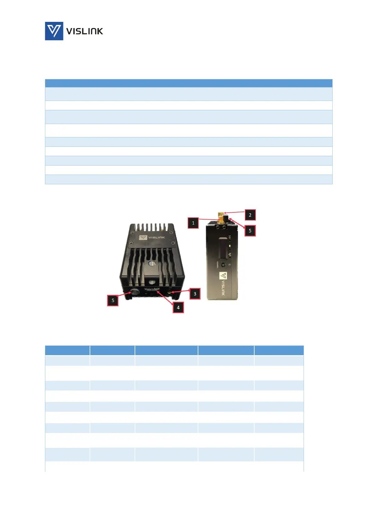
8.5.2. MicroLite 3 Connectors
Figure 25: MLT3 Connectors
Table 7: MLT3 Connectors
Reference
Name
Description
Physical Type
Placement
1
RF Output/
COFDM Output
SMA Female #1
Top of Unit
2
Telemetry
Telemetry
Input/output
SMA Female #2
Top of Unit
3
Video In #1
SDI
DIN
Bottom of unit
4
Video In #2
HDMI
HDMI
Bottom of unit
5
Power In # 1
6.5-28VDC
Lemo 7 pin
Bottom
3 & 4
Audio In
Embedded in SDI
DIN
Bottom of unit
5
User Data In
RS232
Lemo 7 pin
Bottom of unit
5
Camera
Control Data
External control data
Lemo 7 pin
Bottom of unit
6
Wi-Fi
Remote Control
Embedded
Antenna
Embedded
7
Software
USB
Micro USB
Bottom of unit

Table of Contents