Operators Manual
Operation
M55-ML3-UG, Rev A
21
8. Operation
This chapter covers operational information of the Microlite 3 and programming of the
unit (including preset configuration) via the Web page.
8.1. Power Up the Microlite 3
When the installation or set-up is complete as shown in the installation section, connect
the power. The MLT3 requires up to 10 seconds to complete the power-up sequence. It
will boot up in the last state it was turned off at. The OLED initially displays “MICROLITE
3” during startup.
Once powered, the local OLED interface will indicate the following:
• Channel and frequency
• Modulation Type
• Band Width
• Transmission State.
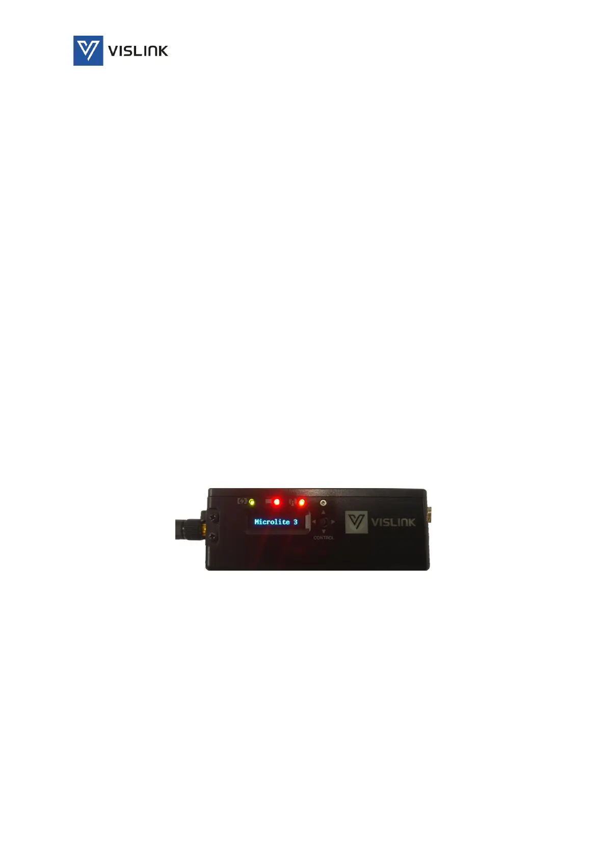
The 3 LED indicators above the OLED display are for:
• DC Power detection (also low or overvoltage alarms)
• Video input detection
• RF Transmission state
Figure 5: Powering up Microlite 3
The OLED display and control joystick and allows you to set the following locally:
• Channels – Set to channels 1-10. The channels are programmed via the webpage
application. The display will indicate the frequency of each channel.
• Transmission State. Locally you may change from Standby, Hi, and Low transmission
states. When on Standby the ‘Transmission’ indicator LED will be red. On ‘HI’ or ‘Low’
the ‘Transmission’ indicator will be Green.
• Modulation - Locally may be set to DVB-T or LMST.
• Bandwidth – Bandwidths may be set to 8, 7, 6, or 5MHz.