Technical Reference Manual-XPM3m Revision Date: August 2014
CALIBRATION PROCEDURE FOR DC DRIVE BOARD (rail width only)
Tools required:
Multimeter (auto-ranging)
Small non-metallic screwdriver
Stop watch or other device to time conveyor movement
Before connecting the power supply:
1. Set the ‘Jumper’ to ‘signal’.
2. Set the MAX SPEED pot to full counter-clockwise.
3. Set the MIN SPEED pot to the 10 o’clock position.
4. Set the IR COMP pot to the 12 o’clock position.
5. Set the TORQUE pot to the 10 o’clock position.
6. Set the signal Pot to the 12 o’clock position.
With the power supply connected:
1. Set the multimeter to VOLTS AC and measure the input voltage to the control. If the voltage is less
than 108V or greater than 132V disconnect the power supply and correct the supply voltage problem.
2. Disconnect the multimeter and set to measure VOLTS DC. Attach leads to the motor side of the
control.
3. Log in to the oven software with the master password. Under Vitronics Soltec, Advanced, Service Mode
Testing, go to the Conveyor tab. Type in a percentage number (0-100) in the box for Conveyor%, then
select either Move in min speed or Move out min speed. Adjust the MIN speed pot so the conveyor is just
barely moving. When done select Stop Rail.
4. Select either Move in Max speed or Move out Max Speed. Adjust the Signal Adjust pot until the conveyor
movement speed is equal to 5 inches per minute. When done select Stop Rail and exit this function.
5. Verify that the width adjust hits setpoint. If not, the minimum speed may be set too low or too high.
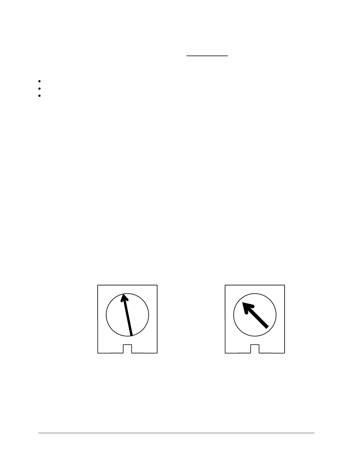
IR COMP TORQUE
MINARIK DRIVE POTENTIOMETER SETTINGS