Technical Reference Manual-XPM3m Revision Date: August 2014
OVEN CONTROLLER
The Oven Control System is comprised of one DI (Digital Input /Output) board, a back-plane board, and one or
more AI (Analog Input) boards. One AI board controls up to 32 process loops. Each additional AI board increases
the number of control loops by 32. The Oven Control System controls the temperature of the cells, drives the
conveyor and rail drive motors, and drives various logic signals through the I/O board.
The Oven Control System receives all of its instructions from the computer by a serial interface.
NOTE: DI OR AI BOARDS SHOULD NEVER BE INSERTED OR REMOVED WITH POWER APPLIED TO THE
VITRONICS SOLTEC CONTROL SYSTEM!
Test procedure for D.C. input voltage:
The power requirements for the Vitronics Soltec Control System, with one AI board, is:
+5.0 VDC @ 2 Amps max (+5.0 to +5.10 VDC)
+15 VDC @ 0.1 Amps max (+12 to +15 VDC)
-15 VDC @ 0.1 Amps max (+15 to -15 VDC)
Shut off circuit breaker F55 supplying 120 VAC power to A1 board.
Remove DI and AI boards from Vitronics Soltec Control System.
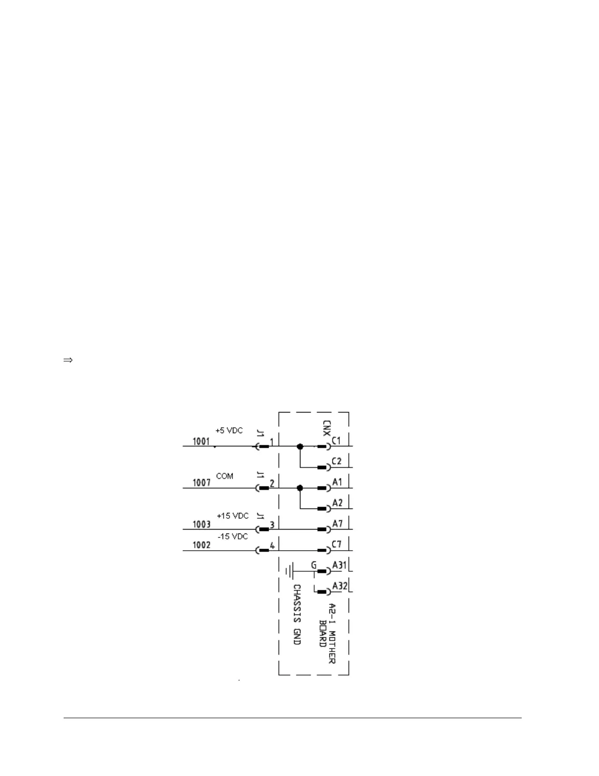
Reactivate 120 VAC power to DC power supply. Using a DC Voltmeter, measure the DC voltages at the
backplane connector: