Technical Reference Manual-XPM3m Revision Date: August 2014
A further test is to use an oscilloscope or volt meter to look at the voltages at P2-1 (TX) and P2-2 (RX). The signal
should switch between a positive value (+5 VDC to +10 VDC) and a negative value (-5 VDC to -10 VDC). The
signal should be free from noise greater than +/- 0.2 VDC.
Noisy communication lines can be corrected by grounding the shield of the communication line, as well as moving
the communication link away from any high voltage sources (especially running parallel to the communications
lines).
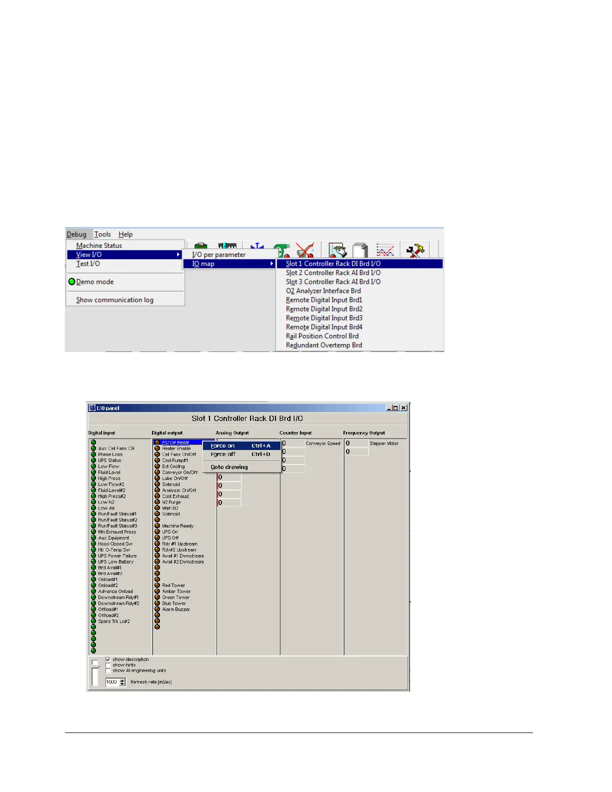
CONTROLLER OUTPUTS (INPUT/OUTPUT BOARD)
The Input/Output board provides the ability to switch 120 VAC power through interposing relays. The oven
controller controls the output status of the Input/Output board As a diagnostic tool, the Input/Output board outputs
may be manually activated one at a time.