Technical Reference Manual-XPM3m Revision Date: August 2014
FUNCTION OF THE FLUX EVACUATION SYSTEM (FLUX FLOW CONTROL
TM
)
N2 Mode -
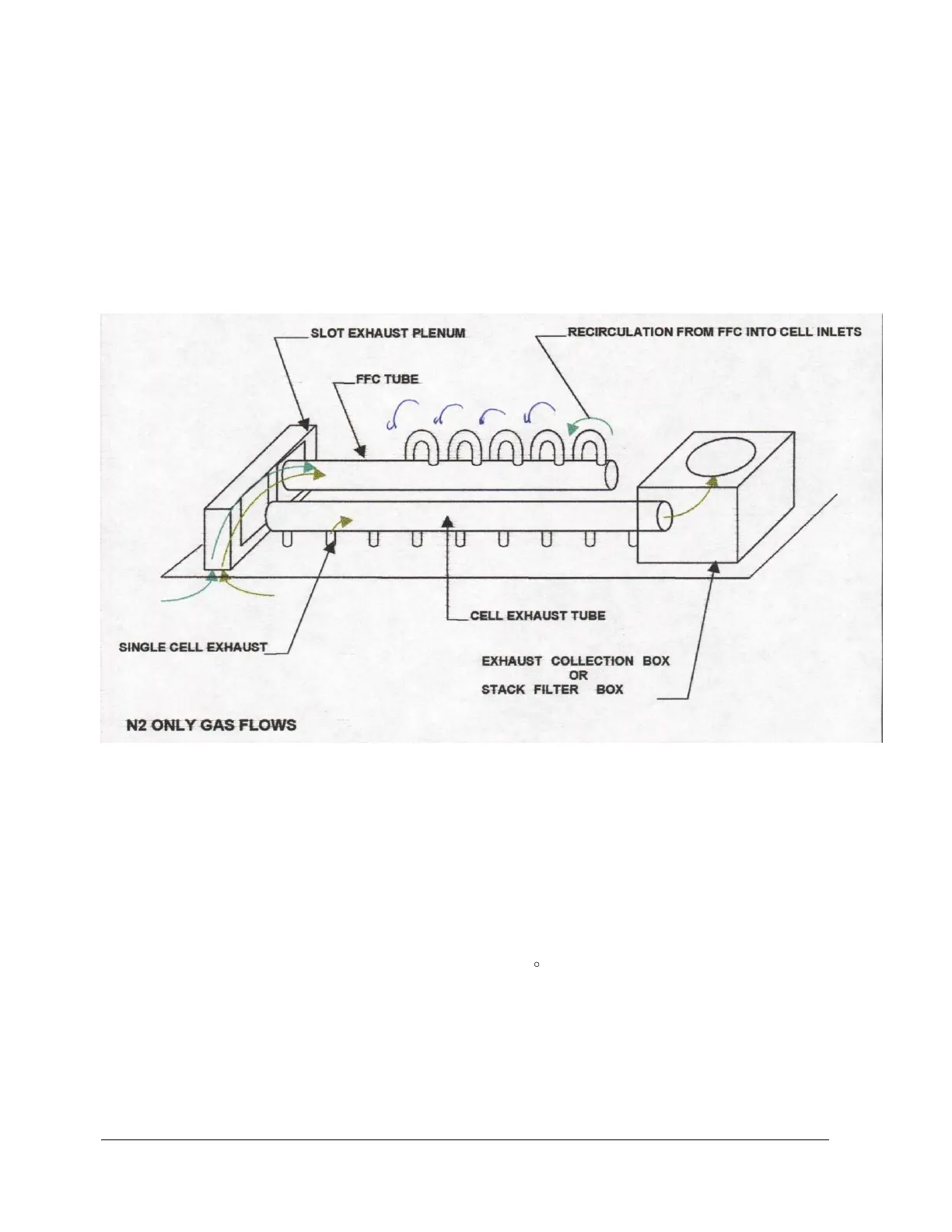
The Flux Flow Control Manifold creates a recirculation loop by drawing gas from the tunnel into the controlled
exhaust plenum between the last heat and first cool zones, and returning it to the preheat and soak zones through
several of the patented individual cell inlets. The force powering this recirculation loop is low pressure at the cell inlet,
created by the cell fan. There are no moving parts to this system.
Flow into the controlled exhaust plenum is biased in favor of drawing from the cool zone side. This is accomplished
by raising the pressure in the cool zone (by inputting a high percentage of the total oven nitrogen consumption into
that area), and by reducing the pressure in the last heated zone (by fully opening the individual cell outlet.) The total
oven exhaust is taken from this one port.
The recirculation loop carries low O2 PPM gas from the first cool zone, into the preheat and soak sections of the
heated zone, maintaining low O2 PPMs throughout the tunnel. The recirculation loop carries out flux contaminants
trying to enter the cooling zones. The higher pressure in the cooling zones inhibits the migration of flux contaminants
from the heated zones. The amount of flow into the controlled exhaust from the last heated zone is at a rate that will
maintain the total recirculation loop gas temperature above 120 C, which prevents condensation.
Exhaust flow out of the oven is maximized in volume, and also positioned in the tunnel at the point of highest flux
concentration (the last heated zone), to maximize the amount of flux contaminant per cubic foot of exhaust.