Technical Reference Manual-XPM3m Revision Date: August 2014
HEATER TESTING PROCEDURE
When a heating problem is suspected, applying this procedure should reduce the time required to eliminate a
number of items that may NOT be responsible for the problem. This will leave a much smaller number of
possibilities for consideration.
To be effective and efficient, the trouble-shooting process does not jump directly to the “answer”, but rather,
eliminates all of the possibilities one-at-time with a systematic approach, until only the “answer” remains.
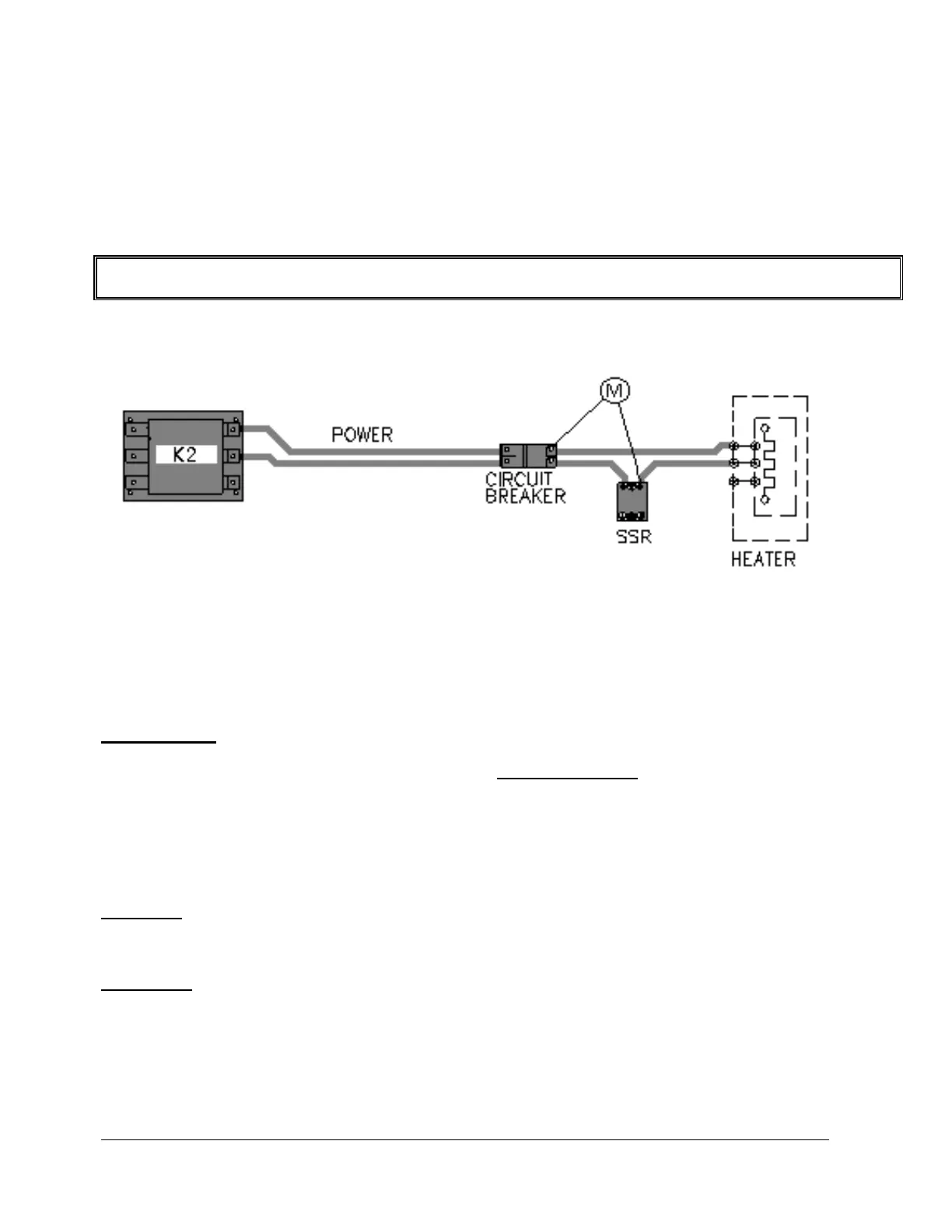
SIMPLIFIED HEATER CONTROL CIRCUIT
EXPLANATION:
Each heater has a Circuit Breaker and SSR. K2 supplies two hot, high voltage conductors to the Line Side of the
Heater Circuit Breaker(s). Both of the current paths are interrupted by the Circuit Breaker when it is open or tripped.
A) On the Load Side of the Circuit Breaker, one of the conductors goes directly to the heater terminals
(HT-A, HT-B, HT-C) on the outside of the Heater Cell.
B) The other conductor is interrupted by the SSR. When the SSR operates, it conducts power from the
Circuit Breaker to the heater terminals (1, 1A, and 2) on top of the Heater Cell.
O.K. TEST: Check the heater(s) for agreement with the “HEATER ELEMENT RESISTANCE REFERENCE
CHART” after disconnecting the supply conductors at the heater terminals
(HT-A, HT-B, HT-C) on top of the Heater Cell. (This does work, however, it is time consuming, and does not check
the conductors between the Circuit Breaker / SSR and the Heater Cell.)
BEST TEST: The heater(s) and conductors can be checked at the Circuit Breakers/SSRs. Reference the
“ HEATER RESISTANCE CHECK LOCATIONS” diagram.