Technical Reference Manual-XPM3m Revision Date: August 2014
ANALYZER OPERATION
E3152502 ASSEMBLY O2 ANALYZER INTERFACE BOARD THEORY OF OPERATION
The Atmel Atmega161 micro-controller is the main component on the board. The Atmega161 has two built in
UARTS. The first UART is used to communicate to an RS485 connection on a multi-drop network through
MODBUS protocol. The second UART is used to communicate directly to an O2 analyzer through an RS232
connection.
The RS485 port is not used with the existing controller since the existing controller does not have additional serial
ports available. Instead, two frequency generator outputs from the micro-controller are used to communicate O2
analyzer data to the existing controller by using two counter inputs on the existing controller. Using the timer/counter
compare outputs of timer 1 and timer 2 of the Atmega161 micro-controller derives the two frequency generator
outputs. Timer 1 has 16-bit resolution and is used to send measured value information, while timer 2 has 8-bit
resolution and is used to send range and alarm information. The Neutronics model 3100 analyzer has six ranges
and automatically changes ranges to measure from 0ppm to 100% concentration.
Dipswitch 4 on S1 is used to enable the use of the two frequency generator outputs through software when the
switch is set to the ON position.
Oxygen analyzer related parameters in the recipe editor are not displayed when the atmosphere setting is for air on
a switching atmosphere oven or on an air only oven. A graphic LED indicator is displayed in the oxygen analyzer
field to indicate that the “ready to measure signal” is present from the oxygen analyzer. The oxygen analyzer
reading is included in trending and data logging.
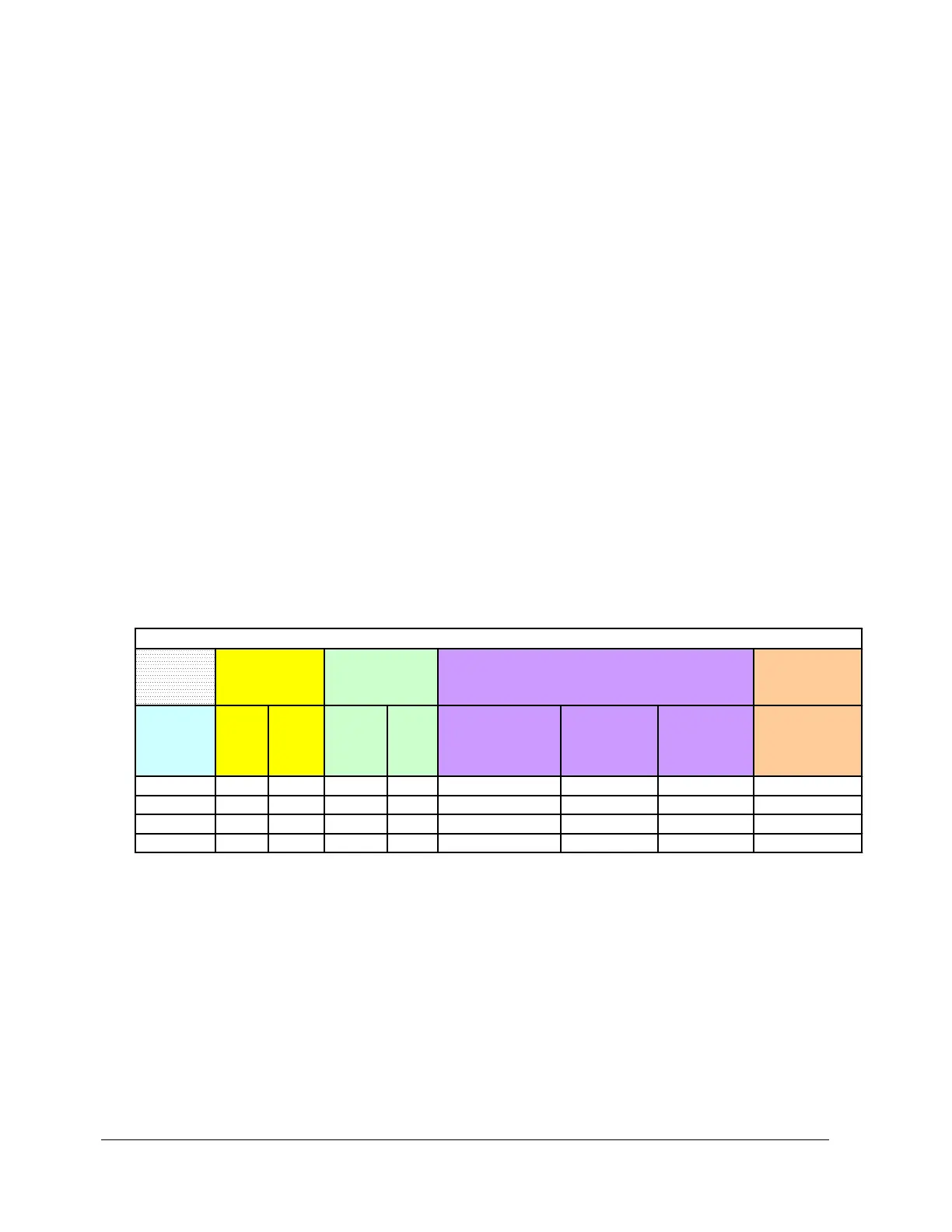
COOLING SYSTEMS
Coolant
Temperature
Control
Customer
Supplied Coolant
& Control
Onboard
Recirculating
System
AC1 S - - - - - - -
EC1 - S S O X - - -
EC2 O O O O - X - X
EC3 O O - X - - X X
XPM3m Cooling Configurations
S = Standard feature
O = Optional
- = Not available
x = Provided with feature or option selected
* Fin Type HX provides maximum efficiency
XPM3m AMBIENT AIR COOLING – AC1 OPTION