Technical Reference Manual-XPM3m Revision Date: August 2014
ADDRESSING DIP SWITCHES ON DI BOARD
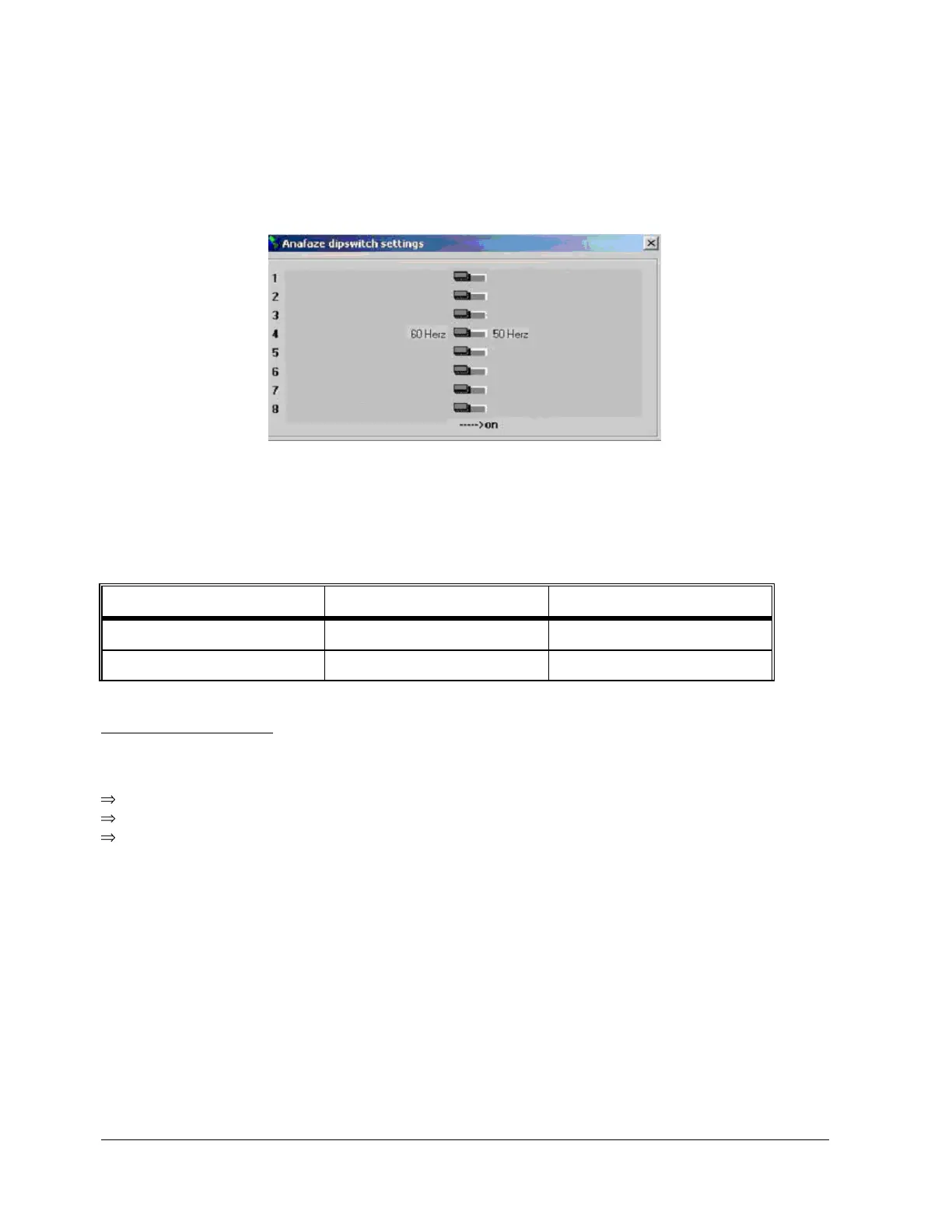
Currently, only dip switch #4 is utilized for 50 or 60 Hz operation. All others are reserved for future use on the
XPM3m. For 60 Hz, dip switch #4 is in the Off position, and for 50 Hz operation, dip switch #4 is in the On position.
ADDRESSING LINKS ON AI BOARD
The AI board contains two series of jumpers, combinations of which dictate the address of the AI board. The
following table identifies the required jumper settings for the first two AI boards in a system:
CONTROLLER STATUS
Upon power up the AI board's status lights should be in the following states:
Green light: On, steady.
Orange light: On, flashing at approximately once per second.
If the status lights are not in the above states check the +5 VDC at the terminal block mounted on the
motherboard.
RS-232 Serial Communication check
Make sure that the RS-232 cable connections from the PC to the controller are correct.
The communication baud rate on the PC oven software is set to 38,400 baud and should never be changed without
consulting the factory.
Verify that the 9 pin d-sub connector is firmly connected on the back of the PC.
Verify that the RS-232 cable to the controller is connected firmly into connector P2 on the front the oven controller
(DI board) and not plugged into connector P1 on the front of the oven controller (DI board).