Technical Reference Manual-XPM3m Revision Date: August 2014
A.C. & D.C. POWER SUPPLIES
CONTROL CIRCUIT TRANSFORMER
The control circuit transformer is a multi-tapped transformer. Determine that the primary conductors to this
transformer are connected in agreement with the supply voltage at the Oven Installation site.
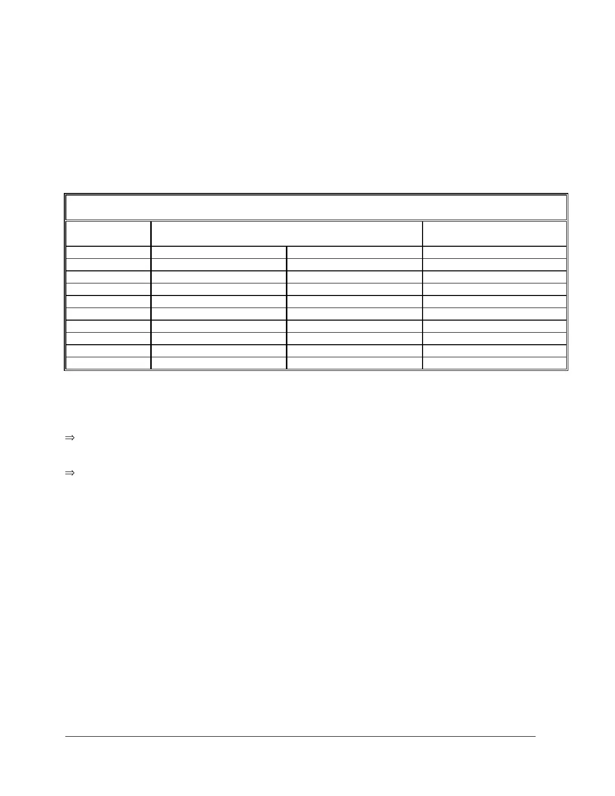
Refer to the table below for transformer tap settings.
SPLIT PRIMARY T1 CONNECTIONS
Test procedure for control transformer voltage
With main power to the oven off, close the circuit breaker on the primary (line) side of the transformer. Open
the circuit breaker on the secondary (load) side of the transformer. Verify that the secondary side of the
transformer's neutral leg is grounded.
Re-apply oven power. Using a Voltmeter set the proper range, measure the output voltage of the single phase
control transformer.(X1 – X4). The output voltage of the transformer should be within +/-10% of the nominal
transformer voltage (i.e. 108 VAC to 132 VAC). If the output voltage of the transformer is outside these values,
the primary taps of the transformer should be adjusted accordingly. When done, close the circuit breaker on the
secondary (load) side of the control transformer.
120 VAC PERIPHERAL SUPPLY (Option)
Two double way AC convenience outlets are located on the oven.
The 120 volt convenience outlets have their hot terminals connected to wire #5, neutral to wire #2, ground to any
ground terminal on the main electrical back panel. These outlets are protected by circuit breaker F54, located on
the main electrical back panel.