Technical Reference Manual-XPM3m Revision Date: August 2014
2- B) INTERLOCKS:
1) Over Temp Switch (es):
BI-metallic snap switch (es) mounted on each Cell Assembly, open when the temperature exceeds
normal operating temperature of the Cell. They are all wired in series and power the coil of K3. (K3
is not shown on this Overview) The coil of K2 is wired through the contacts of K3. When an over
temperature switch opens, voltage to the coil of K3 is lost. This will cause K2 to de-energize, and
ALL power will be removed from ALL heaters. K4 is the Heater Power Enable Relay, and the
voltage for K2 runs through K4, then K3, to K2. (K3 also signals the Controller to shut the Oven
down)
2) Heater Thermocouple (IAS Option)
A Heater mounted thermocouple connected to the Independent Alarm Scanner option. The I.A.S.
output contacts are wired in series prior to the cell over temperature switches and power to the coil
of K3. (K3 is not shown on this Overview) The coil of K2 is wired through the contacts of K3.
When an over temperature condition is sensed, the I.A.S board contacts open and voltage to the
coil of K3 is lost. This will cause K2 to de-energize, and ALL power will be removed from ALL
heaters. (K4 also signals the Controller to shut the Oven down)
3) Heater Thermocouple (Standard)
A Heater mounted thermocouple(s) to sense the temperature of the Heat Cell and connected to the
Controller for heater control.
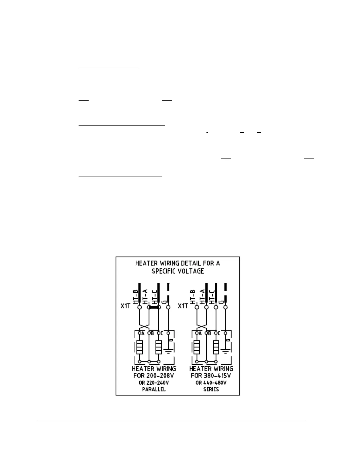
3) HEATERS:
Each Heater Assembly has one large flat Inconel element (resistor) mounted between two aluminum plates.
Each element may be wired in series or parallel, depending on the operating voltage of the oven.
Heater Schematic
See: “Heater Element Resistance Reference Chart” under Heater Testing Procedure in this manual for
resistance values.