Installation
J.M. Voith SE & Co. KG | Instruction Manual/VTA
36
-performance universal joint shaft
Instruction manual (Translation)
G853 en 07/2013, Version1
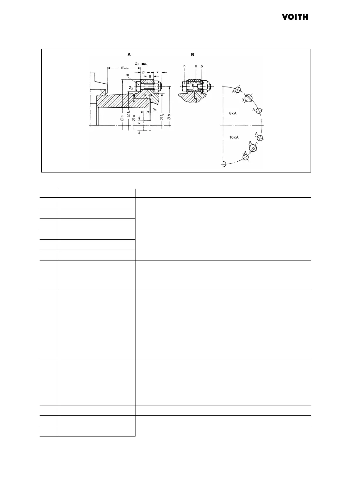
Fig. 6.1: Dimensions of the connecting flange and bolted connections
Ø a Flange diameter Dimensions ( "Dimensions of the connecting flange" area)
Ø b Bolt circle diameter
Ø c Locating diameter
Ø f
a
Flange diameter, bolt side
Ø f
g
Flange diameter, nut side
g Flange thickness
mmin
Minimum distance • Length of the hexagon head bolt m including the height of the
bolt head
• Dimensions of the hexagon head bolt m ( area A, column 4)
m Hexagon head bolt in
accordance with ISO 4014 -
10.9
Hex. nut in accordance with
DIN 985
• Number per connecting flange for universal joint shaft flange:
− Standard design ( area A, column 1)
− with face-key ( area A, column 2)
− with Hirth serrations ( area A, column 3)
• Dimensions ( area A, column 4)
• Tightening torque for a coefficient of friction µ = 0.12 and 90
% utilization of the bolt yield point ( area A, column 5)
n Hexagon head bolt in
accordance with ISO 4014 -
8.8
Hex. nut in accordance with
DIN 985
• Number per connecting flange ( area B, column 6)
• Dimensions ( area B, column 7)
• Tightening torque for a coefficient of friction µ = 0.12 and 90
% utilization of the bolt yield point ( area B, column 5)
o Split sleeve Dimensions ( area B, column 8)
p Washer Dimensions ( area B, column 9)
t Deep centering Dimensions ( "Dimensions of the connecting flange" area)



 To Next Page