J.M. Voith SE & Co. KG/VTA | Instruction Manual
Maintenance
59
-performance universal joint shaft
Instruction manual (Translation)
G853 en 07/2013, Version1
− If possible, remove bearing cover and apply the dial gauge
to the front face of the journal cross. Otherwise apply the
dial gauge to the bottom of the bearing.
− Lift the universal joint shaft with a crane and read the
measured value from the dial gauge.
2. Check measurement values:
Max. axial clearance [mm]
< 500 0.20
500–1500 0.06
> 1500 0.03
Tab. 9.2: Checking axial clearance of the journal cross set
3. If exceeded:
Use thicker locking rings to reduce the axial clearance (order
repair instructions).
Send universal joint shaft to manufacturer.
Insofar as provided: Only have universal joint shaft balanced
by the manufacturer's service personnel or by service
personnel authorized by the manufacturer.
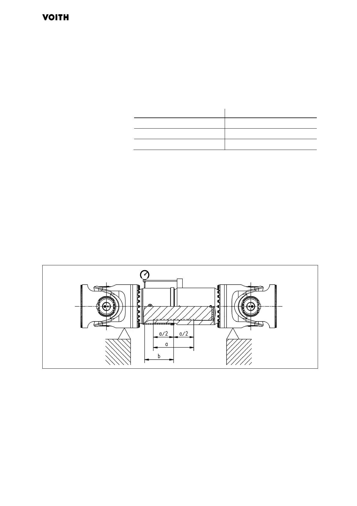
9.3.2 Checking deflection play of the center part
Fig. 9.2: Checking deflection play of the center part
1. Measure the length “a” of the spline profile on the top and mark
the middle.
2. Position the universal joint shaft precisely at the installation
length and put under neath.


 To Next Page