J.M. Voith SE & Co. KG/VTA | Instruction Manual
Installation
49
-performance universal joint shaft
Instruction manual (Translation)
G853 en 07/2013, Version1
6.3 Additional regulations for Hirth serration
For divided flange yokes:
Heed additional documentation (Mounting and dismounting
instructions for divided flange yokes).
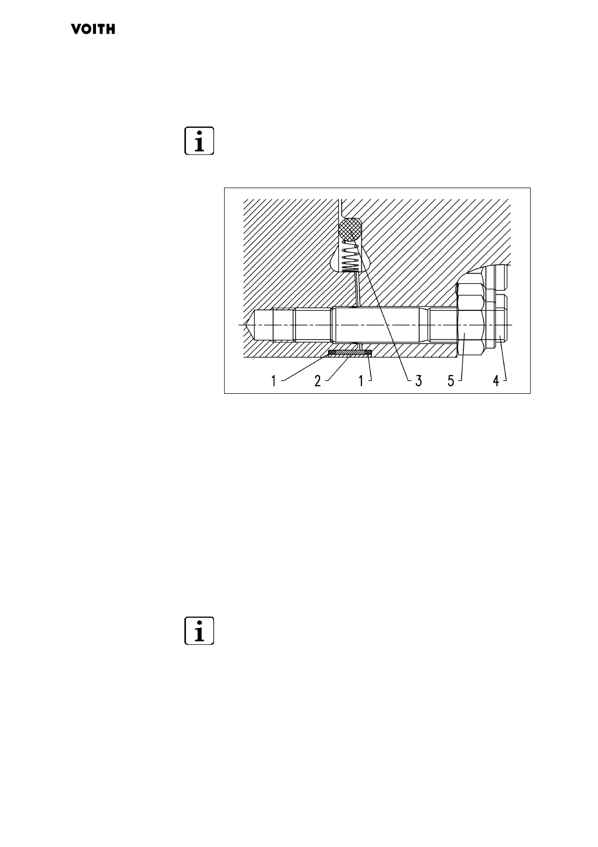
Fig. 6.6: Seals for Hirth serration
1 O-seal (2x) 3 O-seal (optional)
2 Protective ring 4 Screw
5 Nut
1. If present: attach O-seal (3).
2. Attach O-seals (1).
3. Paint Hirth serration thinly with anti-seize (heed here that the
threaded and blind holes are free of anti-seize, otherwise the
friction value in the threads can be reduced by the anti-seize).
4. Heat up protective ring (2) to max. 80 °C and push onto
universal joint over Hirth serration.
If necessary: use hydraulic wrench.
5
. Tighten bolted connection with calibrated torque wrench cross-
wise in stages of 40%, 70%, and 100% of the prescribed
tightening torque:
− for Rota < 550 mm ( Tab. 6.1, page 37)
− for Rota > 550 mm (D
imensional drawing of the
universal joint shaft)
 Loading...