Installation
J.M. Voith SE & Co. KG/VTA | Instruction Manual
40
-performance universal joint shaft
Instruction manual (Translation)
G853 en 07/2013, Version1
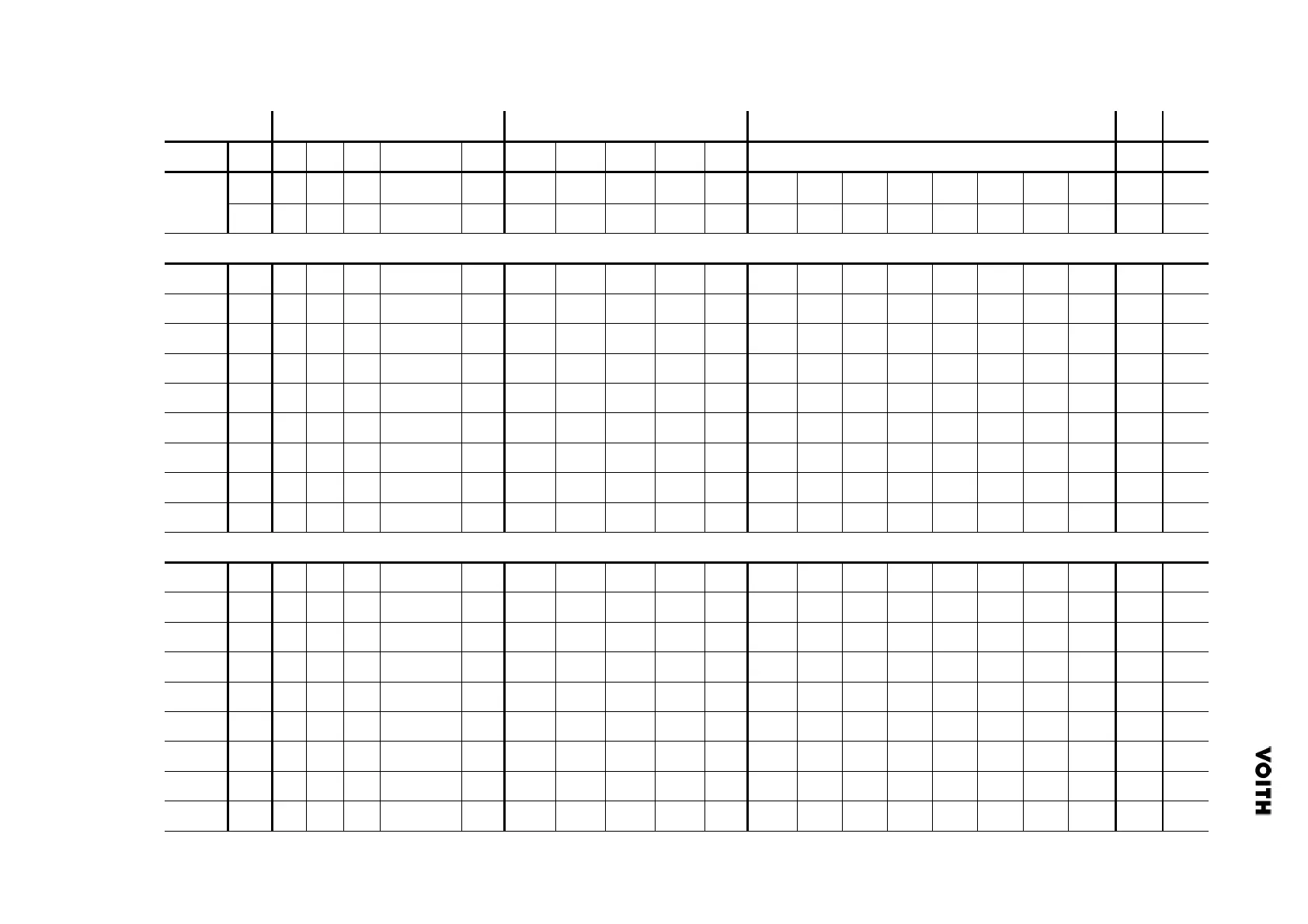
Tab. 6.2: Dimensions of the connecting flange and bolted connections
c
11
c
Types: RT/ RTL/ RTK 1-2/ RF/ RGK/ RFZ/ RZ (design with cross-key)
105
105
125
130
155
170
190
205
250
Types: RT/ RTL/ RTK 1-2/ RF/ RGK/ RFZ/ RZ (design with Hirth serration)
180
200
225
250
280
315
345
370
440
1
,Z
2
10
1
,Z
2
0.06
0.06
0.06
0.06
0.06
0.06
0.1
0.1
0.1
18
20
21
23
24
25
28
31
32
Dimensions of the connecting flanges
a
+0.5
[
mm]
9.5
13
15.5
15.5
16.5
18.5
20.5
23
23
32
40
40
40
50
70
80
90
100
v
25
25
26
31
30
40
38
46
40
25
25
26
31
30
40
36
36
40
t
4
-0.2
5
-0.2
6
-0.5
7
-0.5
7
-0.5
7
-0.5
9
-0.5
-0.5
-0.5
g
20
25
27
32
35
40
42
47
50
20
25
27
32
35
40
42
47
50
f
g
159
176
199
231
261
290
320
350
420
159
175
199
230
261
290
322
350
420
f
a-0.3
171
190
214
247
277
308
342
377
444
171
190
214
247
277
308
342
377
444
[mm]
196
218
245
280
310
345
385
425
492
196
218
245
280
310
345
385
425
492
B (
Fig. 6.1)
5
MA
9
p
8
o
7
n
6
z
A (
Fig. 6.1)
5
MA
265
365
515
695
695
890
270
372
526
710
710
906
4
m
M16 x 65
M18 x 75
M20 x 80
M22 x 95
M16 x 65
M18 x 75
M20 x 80
M22 x 95
3
-
4
4
4
4
6
6
6
8
8
2
-
8
8
8
10
10
10
10
10
10
1
-
-
a
225
250
285
315
350
390
435
480
550
225
250
285
315
350
390
435
480
550
lumn
Size
225
250
285
315
350
390
440
480
550
208
250
285
315
350
390
440
480
550