16 Operating manual Voltwerk VS 3, 4, 5
3 Technical description
ENGLISH
DO_BA_2008_121LB_3ENG_BVo 22.2.10
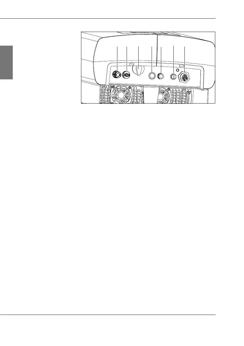
3.1: Connections, DC switch disconnector and button
(1) DC+
Solar power system connection
(2) DC–
Solar power system connection
(3) DC switch disconnector
Switch position 0: there is no power to the power unit
for the string inverter.
Switch position 1: the power unit for the string inverter
is switched on.
(4) Button
Switch on display lighting and operate display menu
(5) CAN In
Connection for previous inverters in a photovoltaic
system, Voltwerk monitoring unit or parameterisation
tool StringInverter Setup
(6) CAN Out
Connection for subsequent inverters in a photovoltaic
system or terminator. If the Voltwerk monitoring unit or
StringInverter Setup is connected, the CAN bus must
be closed with a terminator.
(7) AC Out
Grid connection
(1) (2) (3)
(4)
(5)
(7)
(6)