Do you have a question about the Volvo Penta D5A and is the answer not in the manual?
Explains safety text hierarchy, symbols, and general precautions.
Details daily checks, PPE use, and protection for eyes and skin.
Covers fire safety, spare parts, engine start, ventilation, and hot surfaces.
Covers electrical, welding, cooling, fuel, and battery systems safety.
Details safe cleaning and clutch adjustment procedures.
Explains the purpose and availability of the Operator's Manual.
Details engine warranty coverage and conditions.
Covers fuel, oils, coolant, parts, and strain.
Discusses environmental care and engine data recording.
Outlines special demands for emission-certified engines.
Information on dealers and action service.
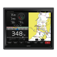
Describes gauges and indicators on the instrument panel.
Explains the function of the ignition switch and key positions.
Outlines initial checks required before first use.
Details general steps and warnings before starting the engine.
Describes the process of starting and warming up the engine.
Provides instructions for using auxiliary batteries.
Guidelines for applying load and avoiding overload.
Explains alarm indicators, acknowledgment, and testing.
Details normal shutdown and emergency stop methods.
Covers checks after shutdown and anti-freezing measures.
Provides a table for symptoms and possible causes of engine disturbances.
Instructions for starting the engine using auxiliary power.
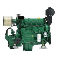
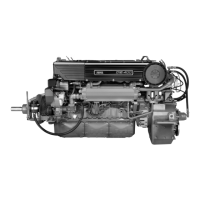
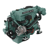
Identifies components for various D5A engine models.
Component identification for D5A T HE model.
Component identification for D5A TA HE model.
Component identification for D5A T RC model.
Component identification for D5A T KC model.
Component identification for D5A TA KC (1-circuit).
Component identification for D5A TA KC (1½-circuit).
Component identification for D5A T HE Marine Genset.
Component identification for D5A TA HE Marine Genset.
Component identification for D5A T RC Marine Genset.
Component identification for D5A T KC (1-circuit).
Component identification for D5A TA KC (1½-circuit).
Component identification for D5A TA KC (2-circuit).
Component identification for D7A T HE Genset Engine.
Component identification for D7A TA HE Genset Engine.
Component identification for D7A T RC Genset Engine.
Component identification for D7A T KC Genset Engine.
Component identification for D7A TA KC Genset Engine.
Component identification for D7A TA KC Genset Engine (different view).
Component identification for D7A T HE Marine Genset.
Component identification for D7A TA HE Marine Genset.
Component identification for D7A T RC Marine Genset.
Component identification for D7A T KC (1-circuit).
Component identification for D7A TA KC (1½-circuit).
Component identification for D7A TA KC (2-circuit).
Covers general inspection and drive belt servicing.
Details adjusting and changing the alternator belt.
Procedures for checking and adjusting valve clearance.
Specifies crankshaft positions for valve clearance adjustment.
Covers oil change procedures and recommendations.
Details oil filter change, level check, and filling procedures.
Covers fuel filter changes and bleeding the fuel system.
Covers adjusting and changing the fuel pump belt.
Details single and dual fuel filter replacement.
Procedures for draining and changing fuel pre-filters.
Explains valve positions for fuel flow control.
Steps for changing fuel filter elements.
Explains freshwater and raw water systems.
Illustrates cooling circuits and drain points for D5A T HE.
Illustrates cooling circuits and drain points for D5A TA HE.
Illustrates cooling circuits and drain points for D5A T RC.
Illustrates cooling circuits and drain points for D5A T KC (1-circuit).
Illustrates cooling circuits and drain points for D5A TA KC (1½-circuit).
Illustrates cooling circuits and drain points for D5A TA KC (2-circuit).
Illustrates cooling circuits and drain points for D7A T HE.
Illustrates cooling circuits and drain points for D7A TA HE.
Illustrates cooling circuits and drain points for D7A T RC.
Illustrates cooling circuits and drain points for D7A T KC (1-circuit).
Details coolant and mixing recommendations.
Procedures for checking and topping up coolant.
Steps for draining coolant and flushing the system.
Procedures for draining the raw water system.
Covers checking and changing the raw water pump impeller.
Details procedures for pump servicing.
Instructions for cleaning the heat exchanger.
Steps for replacing the air filter cartridge.
Procedures for cleaning the compressor and housing.
Instructions for checking and draining condensation.
Covers general system, wiring, main switch, and fuses.
Details battery maintenance, charging, and safety.
Covers replacing the battery and electrical welding safety.
Outlines steps for preserving the engine during storage.
Details conserving lubricating and fuel systems for extended periods.
Steps for preparing the engine after a storage period.
Provides detailed technical data for various engine models.
Details oil capacity, pressure, grade, and fuel specifications.
Covers coolant capacity, temperatures, and water quality.
Details system voltage, alternator output, and battery data.
Shows locations of identification plates on engines and generators.
Details IMO decals and other engine markings.
| Brand | Volvo Penta |
|---|---|
| Model | D5A |
| Category | Marine Equipment |
| Language | English |