OPERATING CONTROLS AND INSTRUMENTS SECTION 3
DD-29/31HF/38HF Vibratory Asphalt Compactors 3-3
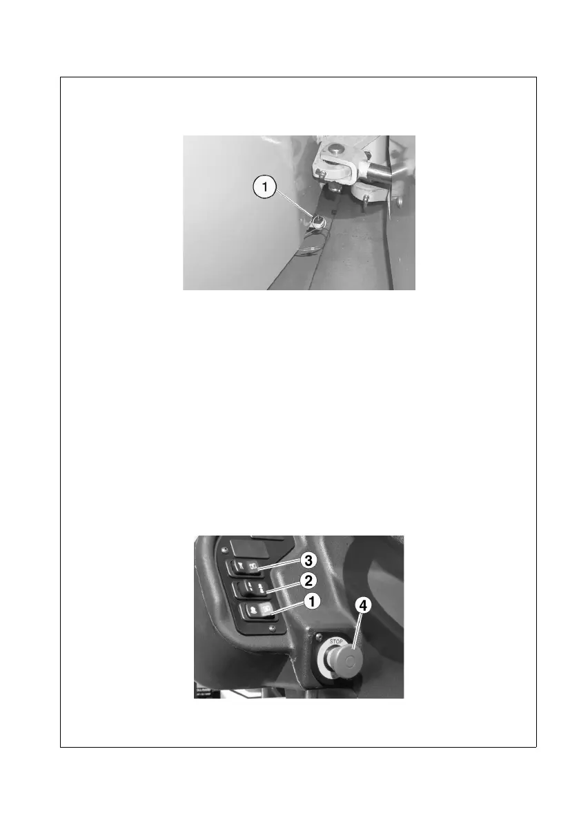
Place the lock bar in the stowed position (1, Figure 3-2) for compaction operations.
Figure 3-2
CONTROLS AND SWITCH LOCATIONS
Refer to Figure 3-3 and Figure 3-4 for locations of the following controls:
Figure 3-3
1. Auto Vibration Switch 7. Indicator Lights
2. Drum Selector Switch 8. Brake Test Switch
3. Water Spray Switch 9. Park Brake Switch
4. Emergency Stop Switch 10. Horn Button
5. Steering Wheel 11. Ignition Switch
6. Hourmeter