46
Installation
Installation
Preparing the installation
1. Read chapter "6.1.2 The internal sensor (WIS)", page 27.
2. Jack up the vehicle at the corresponding wheel positions.
3. Remove the wheel.
4. Use a suitable assembly device to remove the tire.
It is sufcient to pull the tire over the rime on one side; fee access to the drop-centre and valve is
all that is required.
5. Remove the original tire ination valve.
Installation of the internal sensor
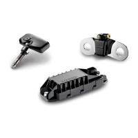
1. Fit the suitable tire ination valve (Figure 1).
Observe the tightening torque specied for the rim and correct alignment of the valve.
Figure 1
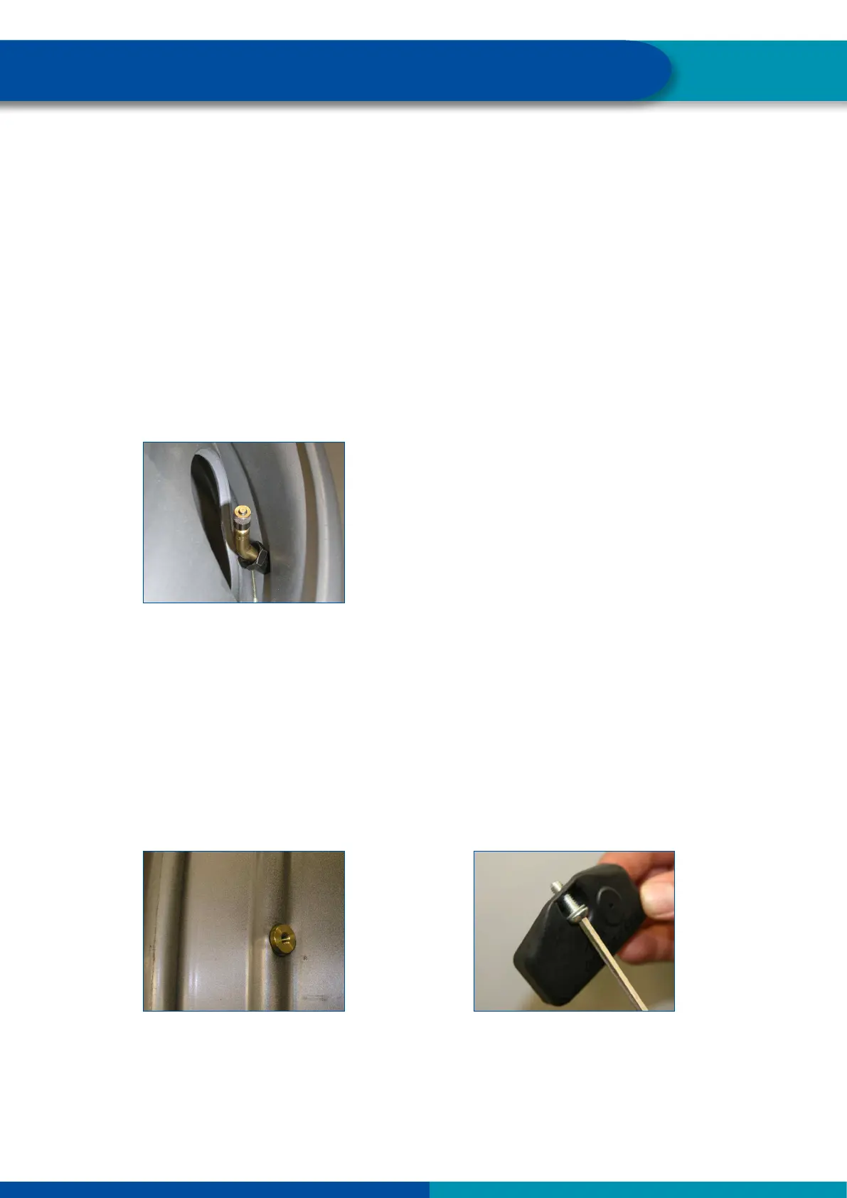
2. After tting the valve, place the internal sensor on the inside of the rim on the valve head (Figure 2)
and secure with the screw (Figure 3). Note the following:
The internal sensor must be aligned parallel to the rim (Figures 4 & 5).
The sensor must make contact over the entire contact area of the valve; in addition it must be
supported at two other points on the rim (3-point assembly) (Figures 6 & 7).
The tightening torque is 4 ±0,5 Nm (Figures 8 & 9). Always use a torque wrench for the exact
torque!
3. Fit the tire according to Chapter "7.5 Assembly of the tire", page 51.
Ö The installation of the internal sensor WIS is completed.
Figure 2
Figure 3