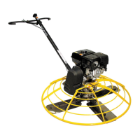
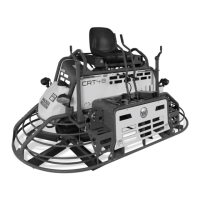
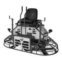
Operation CT 36 / CT 48
wc_tx000373gb.fm 28
3.5 Installing and Adjusting Handles
See Graphic: wc_gr001758, wc_gr003219
On new machines the pipe handle comes assembled with the pitch
control (Twist or Pro-Shift®) (c), stop button (b), throttle (a), screws
(g), and nut (m).
To install the pipe handle assembly:
3.5.1 On machines with the foldable handle, straighten the handle and
tighten the knob (e) to secure the handle in position.
3.5.2 Pull the pitch control cable (j) from bottom end of the tube and remove
the nut from the cable.
3.5.3 Thread the cable through the handle base (f) and over the pulley (h)
as shown.
3.5.4 Attach the pipe handle to the handle base with two M8x65 screws (g).
Torque the screws to 25 Nm (18 ft.lbs.).
3.5.5 Push the Pro-Shift® handle all the way forward (away from the
operator) OR turn the twist pitch control handle counterclockwise as far
as possible. Connect the cable to the fork (k) as shown and adjust the
cable nut (m) so the cable is snug and the trowel blades lay flat (0°
pitch).
3.5.6 Move throttle (a1) to idle position. Remove air cleaner cover. Feed
cable through clamp on recoil cover. Connect throttle cable to engine
throttle bracket by placing z-bend through hole in throttle plate. Clamp
cable into throttle casing bracket. Replace air cleaner cover.
3.5.7 Connect electrical wire on handle to both ends of the engine wire. See
handle instruction sheet for additional detail on installation.
Note: On machines with Wacker engines, do not connect wires in bag
to wires in handle.
3.5.8 On machines with an adjustable handle, position the handle by
loosening the knob (d) and adjusting the handle up or down to suit the
operator. Tighten the knob to secure the handle in position.
 Loading...