31
PC 1025 PRO
EN
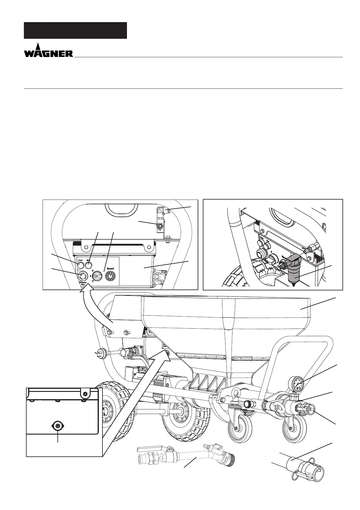
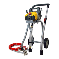
4 EXPLANATORY DIAGRAM FOR PC 1025PRO
EXPLANATORY DIAGRAM
1 Connection for the spraying lance’s air hose 2 Connection for compressed air supply (compressor)
3 Control unit 4 Control panel with selector switch for operating mode
and delivery volume controller
5 Indicator light red (indicates the presence of a malfunc-
tion)
6 Operating light green (indicates that mains voltage is
present)
7 EMERGENCY STOP switch 8 Container
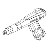
9 Pressure gauge 10 Outlet unit with inside screw pump
11 Connecting coupling for mortar hose 12 Mortar hose with air hose complete
13 Spray lance 14 Flow switch connection
15 Air lter (accessory)
ELEC
PNEUM
Controler
14
12
13
8
9
10
11
1
6
5
2
3
6
4
7
15