32
PC 1025 PRO
EN
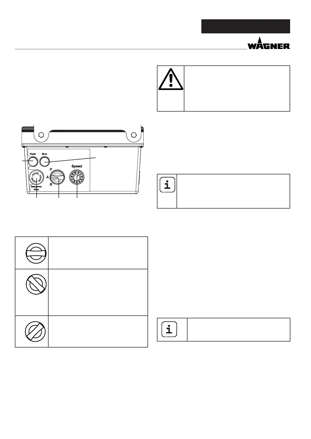
4.1 OPERATING ELEMENTS AND DISPLAYS ON
DEVICE
1 Delivery volume controller 0-10
2 Selector switch for operating mode
3 Indicator light (Error)
4 Operating light (Power)
5 EMERGENCY STOP switch
The delivery volume controller (Fig. 3, 1) is used to regulate
the convey capacity from 0-10 smoothly.
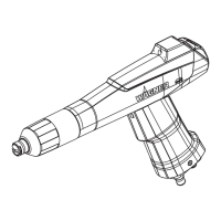
The selector switch (Fig. 3, 2) oers the following modes:
R
“A” position = automatic
Basic setting for control with a pneumatic
spray lance
A
R
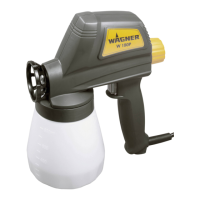
“F” position = manual activation
Switches on the mortar spraying machine.
This setting is required for:
• disassemble stator
• pre-rinsing the mortar hose to improve
the material‘s ability to slide
• cleaning
A
R
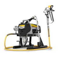
“R” position = reverse gear
This setting is required for:
• assemble stator
• pressure relief manually
Detailed explanation of selector switch use:
If the selector switch is in the “A” position, the PC 1025Pro can
be switched on and o with the air ow regulator on the spray
lance.
If there is no spray lance tted (e.g.: assembly/disassembly the
pump unit ), the machine is switched on using the “F” switch
position and o using the “A” position.
OVERVIEW
Important: control via the selector switch and
material shut-o are treated equally.
The machine can be switched from the “A” po-
sition (control using material shut-o) to “F” at
any time.
We would therefore recommend that only one
person operate the machine.
The operating light (green, Fig. 3, 4) indicates that the machine
is energised and ready.
When the mains plug is connected the PC 1025Pro carries out
a function check. While this is going on the indicator light (red,
g. 3.3) ashes. If everything is in working order, the ashing
stops after about 30 seconds. If the indicator light lights up
during operation, this indicates that there is a malfunction. For
detailed information about this kind of fault, refer to the „Rec-
tication of faults“ section on page 42.
If the selector switch is in the “F” position when
the mains plug is plugged in, the machine will not
switch on.
Briey move selector switch to “A” and then back
to “F” to switch on the machine.
EMERGENCY STOP switch
When the EMERGENCY STOP switch is pressed, the PC 1025Pro
is switched o immediately.
Turn the EMERGENCY STOP switch in order to release it again.
The machine remains switched o after release. To switch it on
again, the selector switch must be briey set to “A” and then
to “F”.
4.2 DRIVE
When an overload occurs, the mortar spraying machine
switches o automatically (red indicator light lights up).
Move selector switch (Fig. 3, 2) to “A” and disconnect mains
plug. Set delivery volume controller (Fig. 3, 1) to „0“.
Wait around 5 minutes, then plug the mortar spraying machine
back in and switch on. Set the delivery volume required.
The drive unit heats up during operation. This
is normal and not a sign of malfunction.
2
1
4
3
5