Making signal connections 1-17
The terms “Connector A” and “Connector B” are generic and do not refer to
pumps A and B.
I/O signal connectors
I/O signals
Signal Description
Switch 1 to Switch 4
(A1, A2, A3, A4,
B1, B2, B3, and B4)
See Event switches on page 1-18.
Ground (A5, A10, B5,
and B10)
Connected to signal ground and used as reference
for outputs.
Gradient Start
(A6 and A7)
An input that initiates the pumps to begin gradient
operation by either contact closure input or 0 volt
input.
Connect the positive input wire to the start gradient
(+) terminal and the negative input wire to the start
gradient (–) terminal.
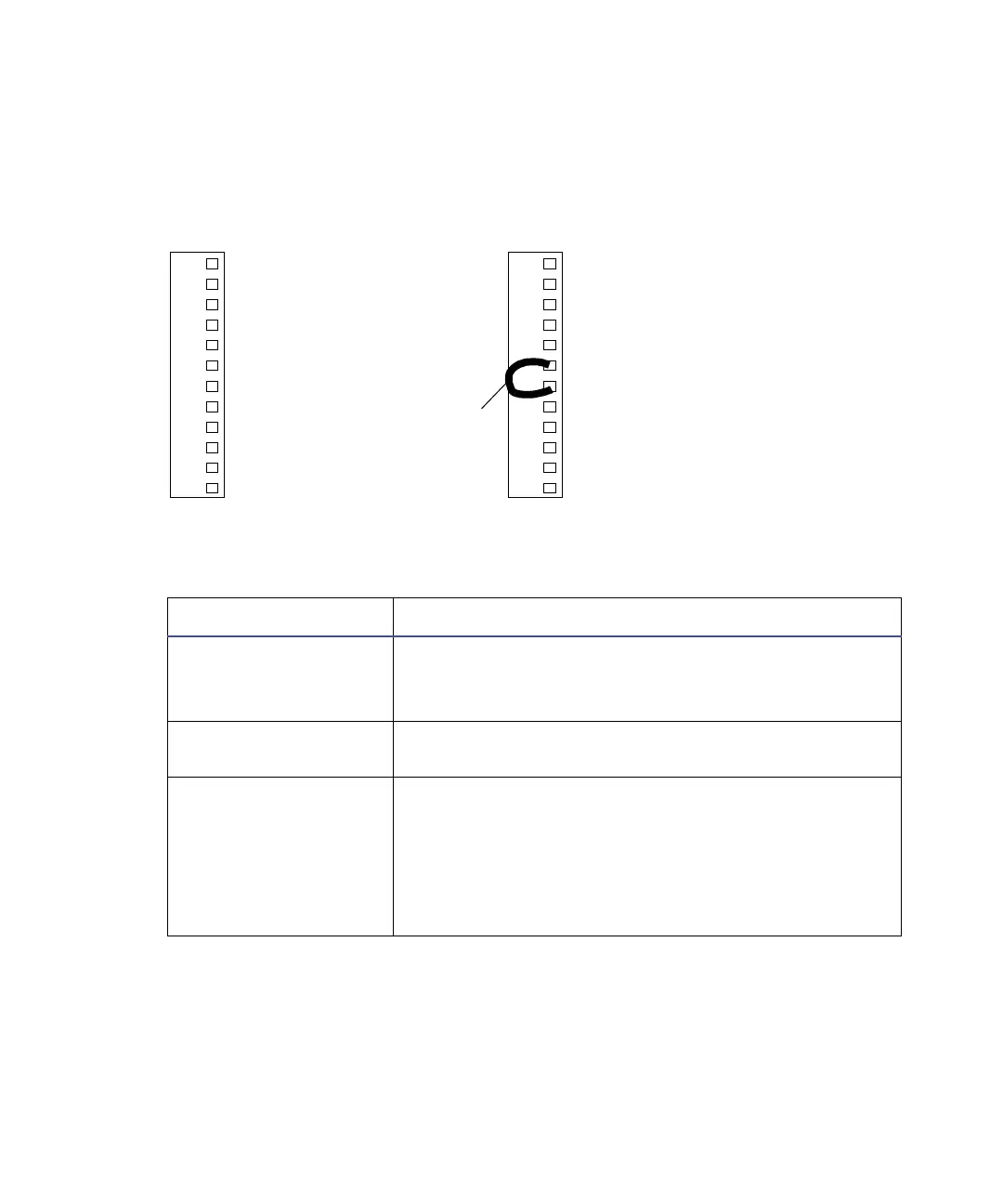
1 Switch 1 (Out)
2 Switch 1 (Out)
3 Switch 2 (Out)
4 Switch 2 (Out)
5 Ground
6 Gradient Start + (In)
7 Gradient Start
– (In)
8 Stop Flow + (In)
9 Stop Flow
– (In)
10 Ground
11 Chart Out 1 + (Out)
12 Chart Out 1
– (Out)
1 Switch 3 (Out)
2 Switch 3 (Out)
3 Switch 4 (Out)
4 Switch 4 (Out)
5 Ground
6 Leak Detector + (In)
7 Leak Detector
– (In)
8 Auxiliary + (In)
9 Auxiliary
– (In)
10 Ground
11 Chart Out 2 + (Out)
12 Chart Out 2
– (Out)
Connector A (top) Connector B (bottom)
Jumper