June 28, 2016, 715003956 Rev. C
Page 83
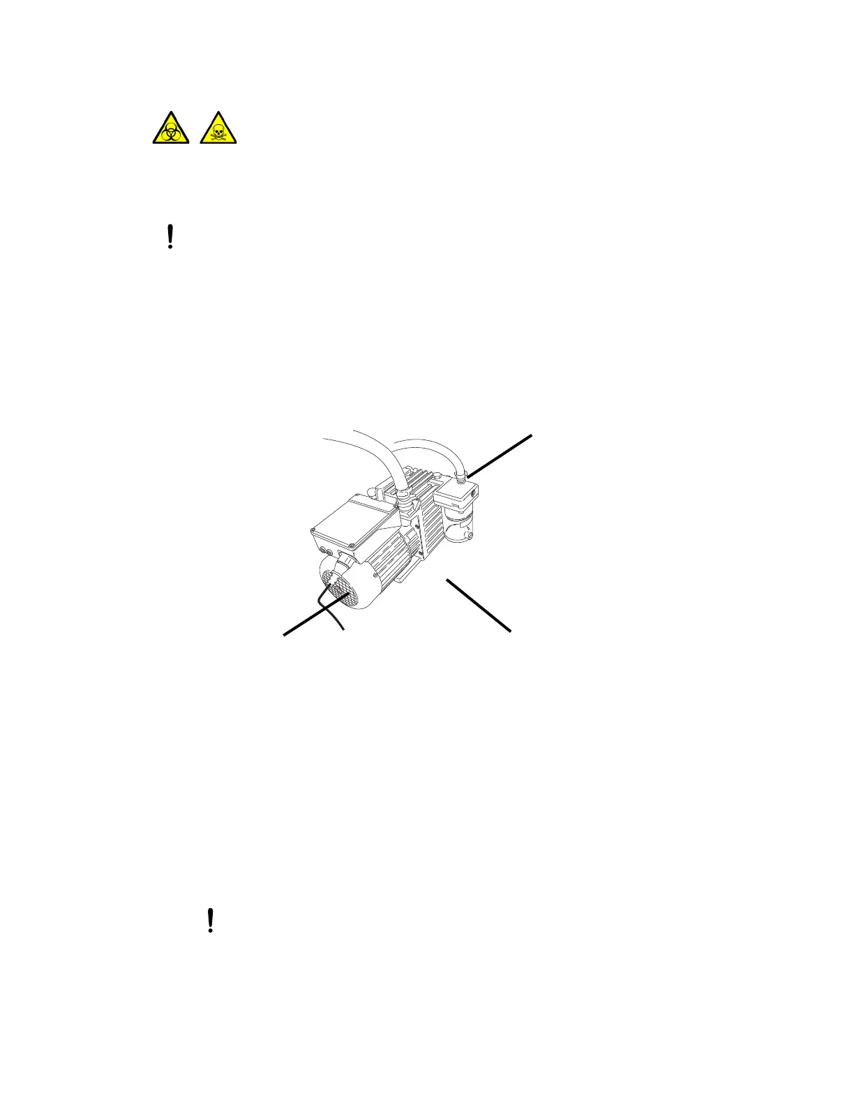
Figure D–3: Backing pump clearance
To connect the backing pump:
1. Place a suitable PTFE drip tray on the floor, within 5 feet of the instrument.
Requirement: The pump must be oriented in a way that allows easy daily access to the gas
ballast valve and oil-level sight glass.
2. Place the pump on the PTFE drip tray.
3. Using the NW16 center ring and clamp, and the 7-mm nut driver, attach the flanged end of a
length of 1-inch ID vacuum hose to the vacuum port on the pump.
4. Using a hose clamp, connect the opposite end of the length of 1-inch vacuum hose in step 3
to the 1-inch OD straight vacuum port on the instrument’s rear panel.
5. Using a hose clamp, connect a length of 19-mm clear PVC exhaust tubing to the pump
exhaust port.
Warning: The pump and its connections can be contaminated with biohazardous and/or toxic
materials. Always wear chemical-resistant, powder-free gloves when performing this procedure.
Notice:
• To ensure the correct operation of the backing pump, it must be installed within 1
degree of horizontal.
• The area where the backing pump is located must have an ambient temperature of 15
to 40 ºC (59 to 104 ºF).
• To ensure proper ventilation, the pump must be installed with the following minimum
clearances:
Notice: To avoid gas leaks, use the sharp knife to cut the PVC exhaust tubing
squarely (that is, perpendicular to its horizontal axis).
Right-side minimum clearance is
15.24 cm (6 inches)
Back-side minimum clearance is
15.24 cm (6 inches)
Front-side minimum clearance is
35.56 cm (14 inches)
Left-side minimum clearance is
15.24 cm (6 inches)