Watlow F4T Install & Troubleshooting • 12 • Chapter 2 Install and Wire
RTD FM [M, L] A - [L, U, Y*] _ _ A - A _ _ _
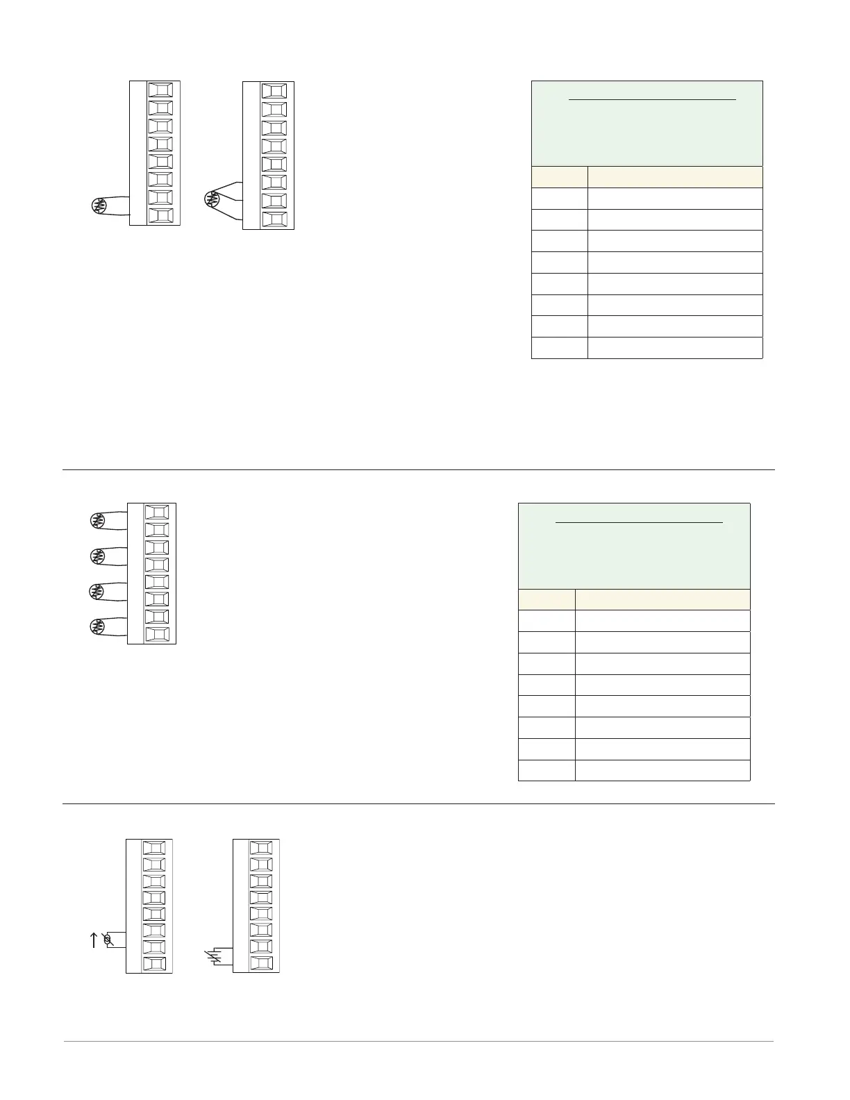
2-wire
T1
S1
R1
S3
S1
3-wire
T1
S1
R1
S2
S3
S1
• 2 or 3-wire platinum, 100
and 1,000 Ω @ 32°F (0°C)
calibration to DIN curve
(0.00385 Ω/Ω/°C)
• RTD excitation current
of 0.09 mA typical. Each
ohm of lead resistance
may affect the read-
ing by 2.55°C for a 100
ohm platinum sensor or
0.25°C for a 1000 ohm
sensor.
• For 3-wire RTDs, the S1
lead (usually white) must
be connected to R1.
* This option does not sup-
port 3-wire RTDs
Lead Wire Resistance
Each wire for 2-Wire
RTDs, not to exceed 10
ohms maximum.
AWG Ohms/1000ft
14 2.575
16 4.094
18 6.510
20 10.35
22 16.46
24 26.17
26 41.62
28 66.17
Note:
3-wire RTD's self-compensate
for lead wire resistance up
to 10 Ω of wire resistance.
RTD (High Density) FMHA - RAAA - A _ _ _
S1
R1
S2
R2
S3
R3
S4
R4
• Platinum, 100 and 1,000 Ω @ 32°F
(0°C) calibration to DIN curve
(0.00385 Ω/Ω/°C)
• RTD excitation current of 0.09 mA
typical. Each ohm of lead resistance
may affect the reading by 2.55°C for
a 100 ohm platinum sensor or 0.25°C
for a 1000 ohm sensor (see table to
right)
Lead Wire Resistance
Each wire for 2-Wire
RTDs, not to exceed 10
ohms maximum.
AWG Ohms/1000ft
14 2.575
16 4.094
18 6.510
20 10.35
22 16.46
24 26.17
26 41.62
28 66.17
Process FM [M, L] A - [L, U] _ _ A - A _ _ _
T1
S1
amperes
-
+
S1
R1
volts
-
+
• 0 to 20 mA @ 100 Ω input impedance
• 0 to 10VÎ (dc) @ 20 kΩ input impedance
• 0 to 50 mVÎ (dc) @ 20 MΩ input impedance
• Scalable
Anderson-Bolds ~ 216-360-9800

 Loading...


