EasyManuals Logo

Watlow F4T Installation And Troubleshooting User’S Guide

Watlow F4T
59 pages
To Next Page IconTo Next Page
To Previous Page IconTo Previous Page
Page #26 background imageLoading...
Page #26 background image
Watlow F4T Install & Troubleshooting 23 Chapter 2 Install and Wire
Output Connections (cont.)
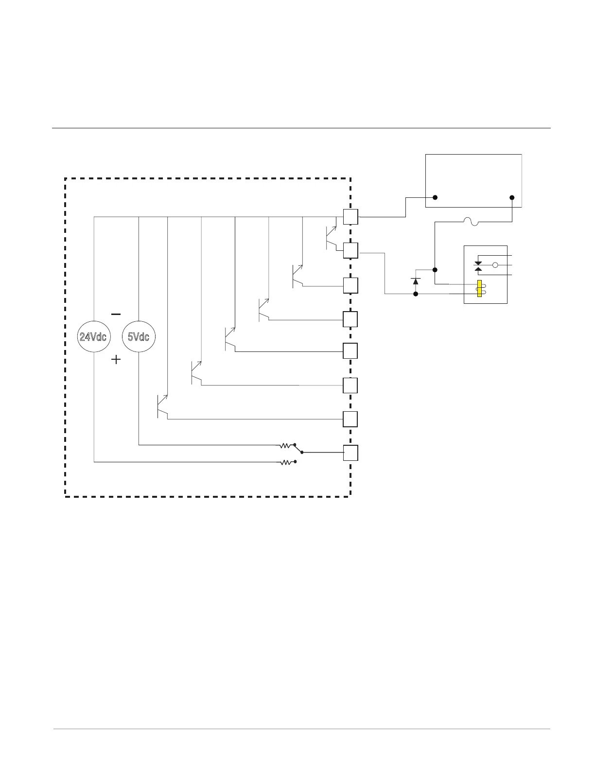
relays. As an open collector output, use an external power supply with the negative wired
to B1, the positive to the coil of a pilot mechanical relay and the other side of the coil
wired to D_. Each open collector output can sink 1.5 A with the total for all open collector
outputs not exceeding 8 amperes. Ensure that a kickback diode is reverse wired across the
relay coil to prevent damage to the internal transistor.
Digital Output - Open Collector Wiring Example
5Vdc
Open Collector Outputs
Internal Circuitry
Power Supply
5 to 32 V(dc)
Relay
+
-
Common
Diode
Fuse
An example fuse is
Bussmann AGC-1 1/2
B1
D6
D5
D4
D3
D2
D1
Z1
User Selectable
Voltage
24Vdc
Anderson-Bolds ~ 216-360-9800
www.anderson-bolds.com

Other manuals for Watlow F4T

Questions and Answers:

Question and Answer IconNeed help?

Do you have a question about the Watlow F4T and is the answer not in the manual?

Watlow F4T Specifications

General IconGeneral
InputsThermocouple, RTD, mA, V
OutputsRelay, SSR, mA, V
CommunicationEthernet, Modbus RTU
Data LoggingYes
CertificationsCE, UL, cUL, RoHS
Control ModesPID, On/Off
Power Supply100 to 240 VAC
Operating Temperature0 to 50°C
Enclosure RatingIP65
Display4.3 in. (109 mm) color touch panel LCD
Control LoopsUp to 4

Related product manuals