32 WWW.WEBER.COM
ROUTINE MAINTENANCE
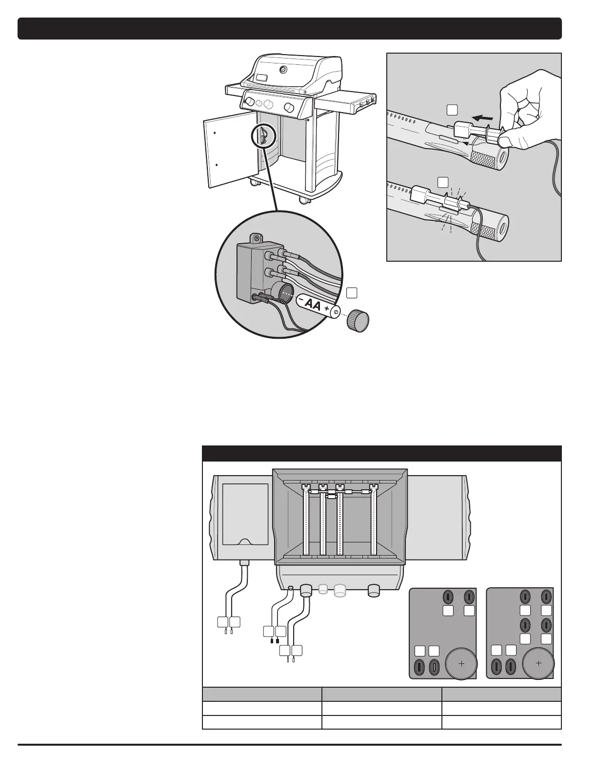
MAINTAINING THE ELECTRONIC
CROSSOVER
™
IGNITION SYSTEM
The igniter module supplies power to the electronic
Crossover
™
ignition system and the side burner with
one igniter button. Whether you are performing routine
maintenance or a troubleshooting check on the ignition
system, read the following to keep your ignition system
working properly.
If the electronic Crossover
™
ignition system fails to ignite,
you'll need to pinpoint where the problem is occurring:
with the gas flow or with the electronic ignition system.
Begin by attempting to match-light your burners. Refer
to “MAIN BURNER IGNITION - Lighting with a Match.”
If match-lighting is successful, the problem lies in the
ignition system.
• Verify that the AA battery (alkaline only) is in good
condition and is installed correctly (1). Some batteries
have a plastic protective wrap around them. This
plastic must be removed before installing battery. Do
not confuse this plastic with the battery label.
• Make sure the igniter wires are properly attached to
the igniter module. Refer to the “IGNITER MODULE
WIRE GUIDE” chart on this page.
• Make sure the ceramic igniter assembly is fully
inserted into burner tube igniter channel (2). If
properly positioned, you will hear a snap (3).
• Make sure the electronic igniter button is working by
listening for clicking and looking for sparks at burner.
If the electronic Crossover
™
ignition system still fails to
ignite, contact the Customer Service Representative in
your area using the contact information on our web site.
Log onto www.weber.com.
1
2
3
IGNITER MODULE WIRE CHART
E-210
™
/S-210
™
E-310
™
/S-310
™
1
2
5 6
E-320
™
/S-320
™
E-330
™
/S-330
™
1
2
3
4
5 6
1
2
34
5
6
BURNER 1 SIDE BURNER IGNITER BUTTON
Black Terminal (1) Blue Terminal (3) Black Terminal (5)
Yellow Terminal (2) Green Terminal (4) Black Terminal (6)