3
Installation and Connection
CFW-11 RB | 3-3
C1
D1
E1
B1
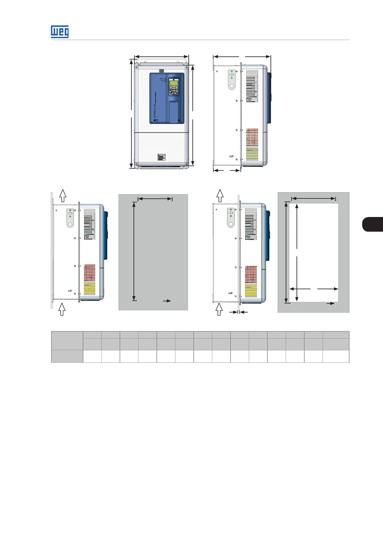
(a) External dimension
b2
a2
c2
Flujo de
aire
Flujo de
aire
a3
d3
c3
Máx. 3 mm
e3
(b) Surface mounting (c) Flange mounting
Model
A1 B1 C1 D1 E1 a2 b2 c2 a3 b3 c3 d3 e3 Torque
(*)
mm
(in)
mm
(in)
mm
(in)
mm
(in)
mm
(in)
mm
(in)
mm
(in)
M
mm
(in)
mm
(in)
M
mm
(in)
mm
(in)
N.m
(ibf.in)
Frame
Size E
335
(13.2)
375
(26.6)
358
(14.1)
168
(6.6)
620
(24.4)
200
(7.8)
650
(25.6)
M8
275
(10.8)
635
(25)
M8
315
(24.21)
615
(24.21)
20.0
(17 7.0)
Tolerance for dimensions d3 and e3: +1.0 mm (+0.039 in).
Tolerance for the other dimensions: ±1.0 mm (+0.039 in).
(*) Recommended torque for the converter mounting (valid for c2 and c3).
Figure 3.1: (a) to (c) - Mechanical installation details - mm (in) - frame size E